Front Suspension
and Steering Handle
|
| Once all parts were
made, it was time for assembly. |
|
11-1a
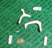 |
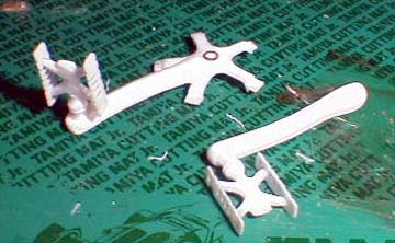
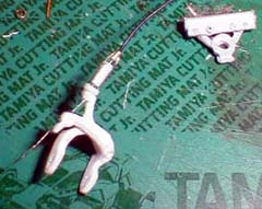
I started with the brake as
shown.
The part at the top was glued to the right arm, and left arm was fixed in-between with a brass rod. I also used brass rod to fix the brake
pad holders.
Each part was left unglued until final position was determined. |
11-1b
 |
11-1c
 |
11-2a
11-2b
 |
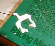
Here is a left crank and pedal
assembly.
Pedal was fixed to the crank with brass rod.
Another pedal was attached to the right crank on the spider
arm. The outer and inner sprockets were glued after this photo was
taken. |
11-3a
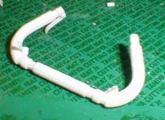 |
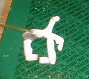
The handle bar is composed of center piece, right and left arm,
two brake handles and two gear handles. All
connections were reinforced with a small brass rod.
|
11-3b
|
11-3c
 |
11-4
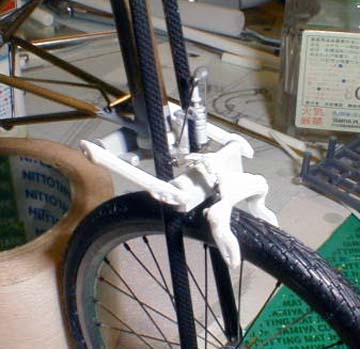 |
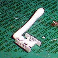
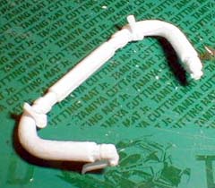
The front brake assembly is shown. I was trying to determine the final position of the brake,
so the brake pads
were still not attached.
|
11-5
|
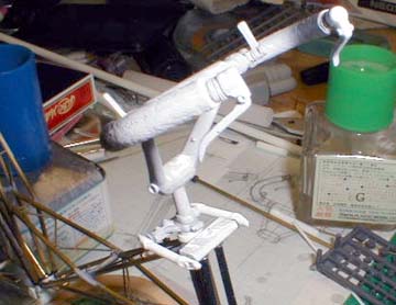
The handle was attached to the top
of the Y shaped steering arm. |
11-6
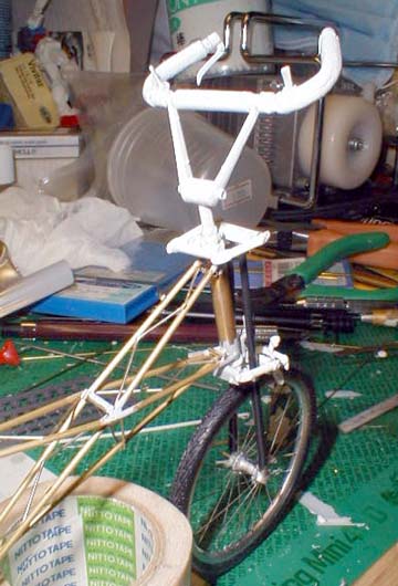 |
The front of the bicycle was
almost finished. |
11-7
 |
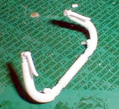
I added the brake wire to the
brake as shown. I added an inverted U shape metal rod to the
brake. Then, I made the wire connector with a 0.3 mm plastic
pipe. Then, I installed the wire to the brake assembly. |
|
|
|
|
|