![]()
![]()
![]()
![]()
![]()

|
|||
| Figure
1.1 shows the arm assembly. Even after they are assembled and painted,
the internal mechanism can be exposed thanks to snap together
construction. The joint which connects the forearm and shoulder is a little too small to hold a big gun. It's tight at the beginning, but it will eventually give up because of the weight of the Guttling Shield, so I'm going to use larger rods and replace the poly caps with a larger one included in Kotobukiya's Polycap set. |
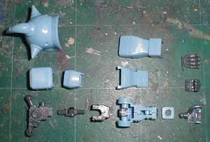 Figure 1.1 Arm Assembly |
||
| The articulation of the leg is good, so it has a great
degree of freedom in posing the model.
The internal structure is visible when posed, so it's recommended to add a few details such as actuators and shock absorbers as well as pipes and wires to enhance already good details. |
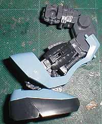 Figure 1.3 Leg Mechanism |
||
| The leg and thigh armors are removable, and when they are removed, fairly detailed mechanisms are exposed as shown in the picture. It would be helpful for those who want to make a diorama of the Gouf under maintenance. Use wash and dry-brush to enhance the detail. | 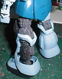 Figure 1.4 Internal Leg Structure |
||
| The shoulder mechanism is connected to the torso by a ball
joint, and this is also a bit weak to hold the gun. It's recommended
to add some support to hold the shoulder up.
The shoulder pivot has a screw, so it can be tightened when necessary. The elbow joint is also weak, so I'm going to replace it with a larger one from Kotobukiya's joint set. The shoulder armor can be posed freely thanks to the ball joint. |
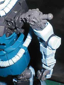 Figure 1.5 Arm Internals |
||
| The external arm assembly is shown. The upper arm
seems a little too small, but that's just a personal taste. I want a
little more modulated curve on the forearm, so it will be extended a
little. The cylindrical elbow joint covers need to be a
bit more pronounced, when compared with the line art.
The whip is made of a wire, so it doesn't have the segmented parts unlike the standard Gouf. The kit includes a separate piece for the tip to fill the hole when the whip is not used.
|
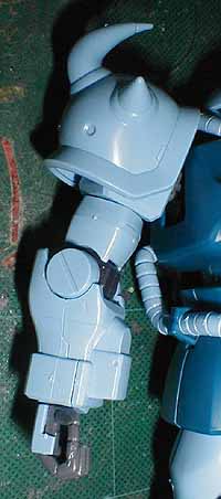 Figure 1.6 External Arm Assembly |
||
| The leg looks good, and it captured the characteristics of the B3 well. The thigh looks a little small, and the contour on the front side is a bit too dull, so I'm going to use polyester putty to enlarge the thigh and change the shape a little. | 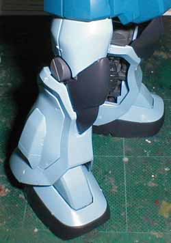 Figure 1.7 External Leg Assembly |
||
| The picture shows the model with most of the armors removed. The model looks dorky as the legs appear shot, but that's because of the camera. | 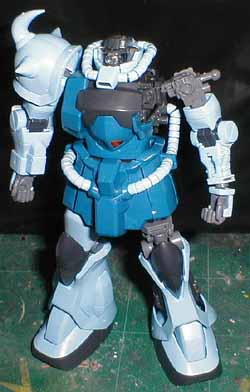 Figure 1.8 Internal Structure Exposed |
||
| The head cover is separated into several pieces, and the top part can be removed to show the internal mechanism. The eye is linked to a disk piece, and it can be rotated, but it's a little difficlut to grab it. It's recommended to add some rod or grip. | 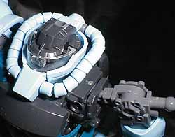 Figure 1.9 Upper Torso Internal Structure |
||
| The chest cover and cockpit hatch are removed. It has
fairly okay details on the torso. It would be nice to add some
parts, that goes inside the extended part to show the difference from the
standard Gouf.
The cockpit detail is minimum, and it's recommended to add control sticks. |
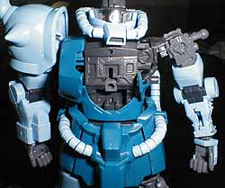 Figure 1.10 Internal Details |
![]()
![]()