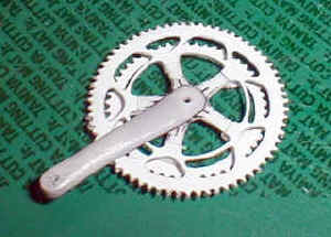
Crank and Sprocket
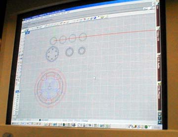
I use Rhino 3D for drawing. Rhino 3D is more suitable for surface modeling for CG, but it's my favorite CAD, because it's easy to use, and it's a powerful enough for hobby use.
 I directly print the image on 0.3 mm plastic sheet, using Alps MD5000.
This isn't quite recommended, because you might brake the printer.
I directly print the image on 0.3 mm plastic sheet, using Alps MD5000.
This isn't quite recommended, because you might brake the printer.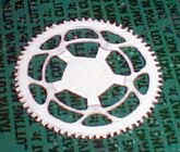
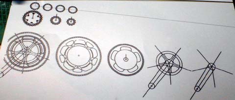
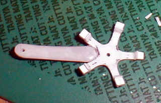
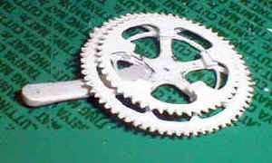
Then, I used OLFA's hobby knife to cut out the openings, and cleaned the edge with a 0.7 mm diameter needle file.
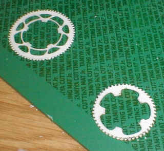
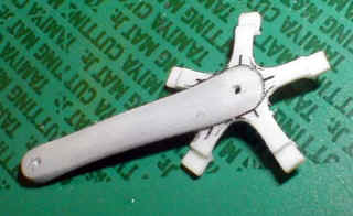
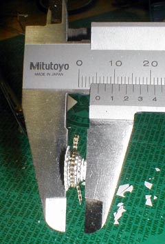
0.3 mm was not thick enough, so I glued the part to another sheet of plastic, and cut out the unnecessary areas.
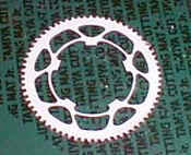
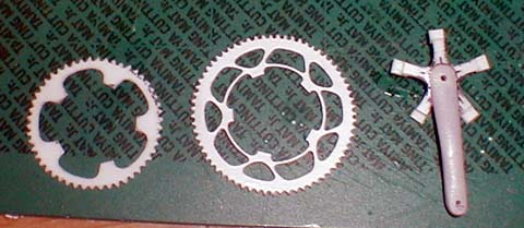
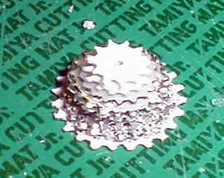
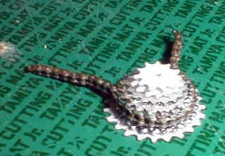
Finished sprockets are shown, one is outer and the other is inner.
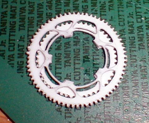
Again, I used 0.7 mm diameter needle file to trim and clean the teeth and corners.
6-6b
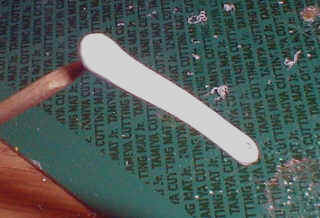
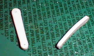
I used files and sand papers to round the edges to the proper shape, while trying to represent the proper section cut.
6-7b
It was glued to the right side crank, and I filled the gap with superglue. Then, I filed and sanded to blend two pieces together.
 All
three components were finished, and it was time to put them together.
All
three components were finished, and it was time to put them together.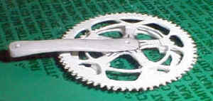
6-11a
6-11b
I used a part in the Audi bicycle model, and I added two sprockets at the top and bottom.
6-11c
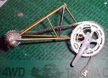 I
wrapped the sprockets with the chain, and it started looking more like a
bicycle.
I
wrapped the sprockets with the chain, and it started looking more like a
bicycle.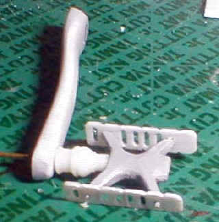
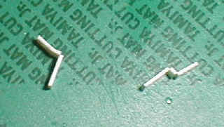
The two plates were also made from plastic sheet. I drilled 0.3 mm holes at the top and bottom of the slits, and the slit was cut open with a sharp knife.
I attached 2.0 mm plastic rod on the DREMEL, and lathed the part, which connects the pedal and crank.
Again, small parts were made with laminated plastic sheet. Some parts can be made with polyester or epoxy putty, and the choice of material is up to individual modelers.