
PRO/II Process Simulation
Natural Gas Liquefaction
by
Mixed Refrigerant (MR) Cycle in Brazed Aluminum Exchangers (Mal-distribution)
by Greenwood
![]()
| |
PRO/II Process SimulationNatural Gas LiquefactionbyMixed Refrigerant (MR) Cycle in Brazed Aluminum Exchangers (Mal-distribution)by Greenwood |
|
Feed Gas Condition
Total Feed gas 6,000kgmol/h (roughly 100ton/h)
Composition:
|
Component |
mol % |
| Nitrogen | 1 |
| Methane | 93 |
| Ethane | 3 |
| Propane | 2 |
| Butane | 1 |
Feed pressure: 60 Bar G
Feed temperature: 40oC
Mixed Refrigerant
Condition
MR flow rate: 19,000kgmol/h
Pressure of HPMR at exchanger inlet: 49.5BarG
Pressure of LPMR at exchanger inlet: 3 BarG
Temperature: 40oC
MR Composition:
|
Component |
mol % |
| Nitrogen | 12 |
| Methane | 27 |
| Ethane | 26 |
| Propane | 20 |
| Butane | 15 |
Simulation Model
It was assumed that liquid tends to flow into 1/3 of BAEX installed in parallel. This liquid rich group is named E-1. The other group is named E-2. Under even distribution, E-1 receives 33.33% of HPMRL1 and HPMRV1. But under mal distribution, E-1 receives more HPMRL1 and less HPMRV1. It was assumed that the quantity of HPMRV1 may be determined to keep same moral flow of HPMR1. Reason of this is volumetric flow of HPMR1 is kept fairly constant due to pressure balance.
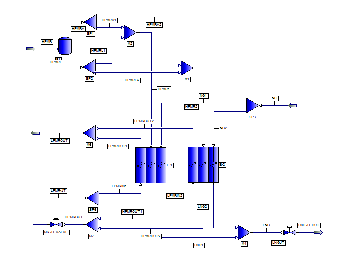
PRO/II model
Summary of Simulation
| Liquid Distribution | unit | total flow | even | mal | mal | mal | mal |
| HPMRL1/HPML mol ratio | % | 100 | 33.33 | 40.00 | 45 | 50 | 55 |
| HPMRV1/HPMV mol ratio | % | 100 | 33.33 | 29.76 | 27.09 | 24.41 | 21.74 |
| LPMR1/LPMR mol ratio | % | 100 | 33.33 | 33.33 | 33.33 | 33.33 | 33.33 |
| NG1/NG mol ratio | % | 100 | 33.33 | 33.33 | 33.33 | 33.33 | 33.33 |
| HPMRV1 | kgmol/h | 12,375 | 4,125 | 3,683 | 3,352 | 3,021 | 2,690 |
| HPMRL1 | kgmol/h | 6,625 | 2,208 | 2,650 | 2,981 | 3,313 | 3,644 |
| HPMR1=HPMRV1+HPMRL1 (keep constant) | kgmol/h | 19,000 | 6,333 | 6,333 | 6,333 | 6,333 | 6,333 |
| LPMRINT1 | kgmol/h | 19,000 | 6,333 | 6,333 | 6,333 | 6,333 | 6,333 |
| NG1/NG | kgmol/h | 6,000 | 2,000 | 2,000 | 2,000 | 2,000 | 2,000 |
| E-1 | |||||||
| Duty1 | Tcal/h | NA | 37.58 | 37.53 | 37.5 | 37.47 | 37.43 |
| weighted LMTD1 | C | NA | 7.35 | 6.89 | 6.51 | 6.09 | 5.63 |
| MITA1 | C | NA | 2.40 | 2.28 | 2.19 | 2.1 | 2.02 |
| UA1 | Mcal/h C | NA | 5,114 | 5,545 | 5,756 | 6,152 | 6,650 |
| E-2 | |||||||
| Duty2 | Tcal/h | NA | 75.17 | 75.22 | 75.26 | 75.29 | 75.33 |
| weighted LMTD2 | C | NA | 7.35 | 7.56 | 7.7 | 7.85 | 7.99 |
| MITA2 | C | NA | 2.40 | 2.47 | 2.52 | 2.57 | 2.58 |
| UA2 | Mcal/h C | NA | 10,230 | 9,956 | 9,769 | 9,590 | 9,429 |
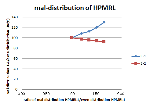
| mal-distribution HPMRL1/even distiribution HPMRL1 | - | NA | 1 | 1.20 | 1.35 | 1.50 | 1.65 |
| mal-distribution UA1/even distribution UA1 | % | NA | 100 | 108.43 | 112.55 | 120.30 | 130.04 |
| mal-distribution UA2/even distribution UA2 | % | NA | 100 | 97.32 | 95.49 | 93.74 | 92.17 |
Conclusion
Acknowledgment
Author is grateful to Invensys Systems Japan, Inc. for letting author to use PRO/II v9.
August 22, 2011
Rev. August 24, 2011