During a preparation of Cost of Various Solar Power, Mr. Greenwood used published data of their Solar Tower technologies by SolarMission Technologies, Inc. Then he did more detailed analysis of this system using well known engineering correlation.
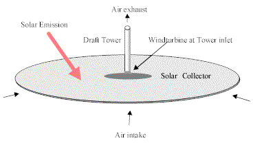
This technologies first developed by West German Ministry of Research and Development utilize Solar Collector, Draft Tower and Windturbine as illustrated in the following figures.

Prototype test was conducted in Manzanare, Spain in 1982 to1989. Based on this experience first commercial plant to be built in Wentworth Shire, Australia is now under study by EnvironMission Ltd.
As published data by EnvironMission Ltd are limited, Mr. Greenwood built a computer model to simulate fluid dynamic and thermo dynamic behavior of the system and back checked published data. All equations are very common found in engineering hand book. He used correction parameter a for correcting contraction coefficient x at the inlet of turbine.
Model of Solar Collector
Solar collector has a very simple design. Plain flat land is only covers by thin plastic film having some space between the cover and terrain.
Solar Emission defined by IEC60904-1 AM1.5 is 1kW/m2.
Surface area of the collector is;
Ac=(p/4) dc2 (m2)
Here, dc is a diameter of the collector (m)
Heat from the sun, Q is;
Q=860.1 Ac (kcal/h)
Absorbed heat, Qc by air is;
Qc=Qhc/100
Where, hc is absorption efficiency of the collector.
and
Qc=G (ii-io) (kcal/h)
Here, G (kg/h) is mass flow of air flowing through the collector and i is enthalpy corresponding to inlet and outlet temperature t. Enthalpy of the air was calculated by following equation neglecting moisture content.
i=(0.79 (6.5 (273+t)+0.001(273+t)2/2)+0.21 (8.27(273+t)+0.000258 (273+t)2/2+187,700/(273+t)))/28.8 (kcal/kg)
defined as,
hc=100 Qc/Q (%)
Assuming Ideal gas, specific volume of air was calculated by following equation.
v=(22.4/28.8) ((273+t)/(273+0) (10,332/pi) (m3/kg)
Here, pi (Kg/m2) is the collector inlet pressure.
Air density r is,
r=1/v (kg/m3)
Friction Loss in the Collector, Fh and pressure drop, Dph was calculated by Fanning's equation.
Fh=f 4 (u2/2 gc) (rc/dh) (Kg m/kg)
Dph=r Fh (Kg/m2)
Here, rc=dc/2 is a collector radius, u is a average velocity and dh is hydraulic diameter of the collector.
At the inlet of collector,
ai=p Zi dc (m2)
ui=(G/3,600) vi /ai (m/sec)
dhi=2 Zi pdc/(Zi + pdc ) (m)
At the outlet of collector,
ao=p Zo dc (m2)
uo=(G/3,600) vo /aio (m/sec)
dho=2 Zo 1.4pdt/(Zo + 1.4pdt ) (m)
Hence,
u=(ui+uo)/2 (m/sec)
dh=(dhi+dho)/2 (m)
Here, dc is a collector diameter Zc is average height of collector cover.
Fanning friction factor is a function of Reynolds Number Re=r u dh/m
1/SQRT(f)=-4log10((e/dh)/3.71+1.26/(Re SQRT(f)))) (-)
Here, e is average roughness of earth and cover in mm.
As the region is in turbulent flow, following equation is applicable for contraction loss at the mouth of turbine.
Fc=a x (ui2-uo2)/2 gc (Kg m/kg)
Dpc=r Fc (Kg/m2)
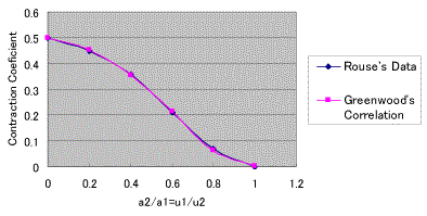
Here, Coefficient of Sudden Contraction x is taken from following Rouse's Data in Perry's Hand Book. For the purpose of automated calculation, Greenwood's equation that match the data well was created.
x =0.5 EXP((-10(u1/u2)2+10(u1/u2 )-5) (u1/u2 )2.2 ) (-)

Coefficient of Sudden Contraction, x v.s. Area Reduction ratio a2/a1
a is a correction factor for smooth contraction. This could be back calculated from published data.
Windturbine Model
Theoretical power, E recovered by windturbine installed in a duct is described as;
E=m (ui2-uo2)/2 gc (Kg m/sec)
Here, inlet velocity head is ui2/2 gc and outlet velocity head is uo2/2 gc and air mass m is described as;
m=G/3,600 (kg/sec)
When turbine blade efficiency is hb , shaft power output is;
Shaft Power=(hb/100) E/101.972/1,000 (MW)
When hg is generator efficiency, generator output becomes;
Generator Output=(hg/100) Shaft Power (MW)
When ui is design inlet velocity, and n is number of turbines and air specific volume is vi ,
ui=(m/n) vi /a = (m/n) vi/ (pr2) (m/sec)
Radius, r of windturbine is,
r =SQRT((m/n) vi/(pui )) (m)
Velocity, uo in the draft tower is determined by diameter of the draft tower dt.
uo=m vo/at (m/sec)
at=(p/4) dt2 (m2)
Turbine Power Extraction Ft and Dpt are;
Ft=(ui2 - uo2)/2 gc (Kg m/kg)
Dpt=r Ft (Kg/m2)
Draft Tower Model
Ambient temperature at the top of the tower is assumed by following equation published by NASA.
to + 273=(ti + 273) - 0.0065 Z (oC)
Here, Z (m) is the height of the tower.
Atmospheric pressure at the top of the tower is assumed by following equation also published by NASA.
po=pi (1- 0.0065 Z/(t0 + 273)5.2569 (Kg/m2)
Friction loss of air with tower wall Ff and Dpf are described by Fanning's Equation.
Ff=f 4 (u2/2 gc) (Z/dt) (Kg m/kg)
Dpf=r Ff (Kg/m2)
As Reynolds number Re=r u dt/m shows turbulent region, friction factor f is calculated by following equation applicable for rough surface in turbulent region.
f=(1/(2.28-4log (e/dt)))2 (-)
Here, e is rough surface height in mm. Air viscosity m=0.018 c.p.=0.000018kg/m sec.
Velocity head loss at the top of the tower Fe and Dpe are described by following equation.
Fe=uo2/2 gc (Kg m/kg)
Dpe=r Fe (Kg/m2)
Heat Loss Qt across tower wall is
Qt=At (k/z) (ti - ta) (kcal/h)
At= p dt Z (m2)
Where thermal conductivity of rock wool insulation k = 0.05 (kcal/m/h/C), thickness of the insulation is z (mm), and temperature difference is ti-ta (deg. C).
Turbine inlet contraction loss Fc, and Friction loss in the tower Ff warms air. Such heat Qf is;
Qf=G (Fc + Ff)/J (kcal/h)
Here, J=423 (Kg m/kcal)
Turbine loss also warms up air. Heat generated by loss is described by;
Qb=E (1 - hb/100 ) /(G/3,600) (kcal/h)
Due to all those heat tower top temperature to is;
to=ti + (-Qt + Qf + Qb)/(G cp) (oC)
Here, specific heat of air is calculated by;
cp=(0.79 (6.5+0.001(273+t)) + 0.21( 8.27+0.000258 (273+t)-187,700/(273+t)2))/28.8 (kcal/kg C)
Pressure Balance
Driving force of draft effect of the tower, Dpdl is;
Dpdl=(ro -ri ) Z (Kg/m2)
Where ro is average ambient air density and ri is average air density inside the tower
Overall friction, contraction and expansion loss is
Dpl=Dph + Dpc + Dpt+ Dpf + Dpe (Kg/m2)
At equilibrium state, following equilibrium will be established.
Dpdl= Dpl (Kg/m2)
Coding of 170 lines were made on Excel sheet. Heat absorption efficiency of the collector, hc was calculated straight from air mass flow rate, G obtained from the velocity in the Tower. Friction factor, tower outlet temperature reflecting friction loss and heat loss turbine and turbine inlet velocity matching vuoyancy and friction were calculated by Solver.
Detailed Model of Solar Collector
From temperature rise in the collector and velocity in the tower, collector heat absorption efficiency, hc could be back calculated. More detailed heat transfer between sun, natural wind, cover, air flowing under cover and earth surface were investigated.

Infrared fraction of the solar emission will be absorbed by cover as described below;
Qsc= as Q (kcal/h)
Where as is absorptivity of solar emmision by cover.
High frequency portion of the solar emission, Qse corresponding to 6,000 deg. C, almost pass through the cover and reach earth surface.
Qse= Q - Qsc = Q (1 - as ) (kcal/h)
When, hs is defined as transparency of the cover as regard for solar emission, hs = (1 - as ) , then
Qsc = Q (1-hs) (kcal/h)
Qse= Q hs (kcal/h)
When temperature of the cover is tc, the black body emission of the cover is expressed by Stefan-Botzmann's equation
Ec=4.88 ((tc+273)/100)4 (kcal/m2 h)
When emissivity of the collector is ec heat loss from the cover to universe Qcu, and heat loss from the cover to earth Qce becomes
Qcu=Qce=Ac ec Ec (kcal/h)
When temperature of the earth surface is te, the black body emission of the earth is expressed by Stefan-Botzmann's equation.
Ee=4.88 ((te+273)/100)4 (kcal/m2 h)
When emissivity of the earth surface is ee, = ae , the heat loss from the earth Qe becomes
Qe=Ac ee Ee (kcal/h)
Some portion of the heat is again absorbed by cover as follows;
Qec=Qe ac (kcal/h)
The rest of the heat is permanently lost to the universe.
Qeu= Qe (1-ac) (kcal/h)
When, hc is defined as transparency of the cover with respect to infrared ray, hc= (1-ac) , then
Qec=Qe (1-hc) (kcal/h)
Qeu=Qe hc (kcal/h)
Forced convection heat transfer coefficient between air and flat earth or cover, hf is calculated by Nusselt type equation.
hf=0.036 Re0.8 Pr(1/3) (k/rc) (kcal/m2 h oC)
Where, Reynolds Number, Re=r u rc/m and Prandtle Number, Pr =cp m 3,600/k, air thermal conductivity k=0.0276(kcal/m h C), and diameter of the collector, rc(m).
Natural convection heat transfer coefficient between air and flat earth, hn is;
hn=1.3 Dt1/3 (kcal/m2 h oC)
Using this coefficient, heat transfer between earth surface and air could be;
Qea=Ac (hf + hn) LMTDea (kcal/h)
Where, LMTDea is mean logarithmic mean temperature difference between earth and air.
LMTDea=( Dti-Dto)/(2.3log(Dti/Dto)) (oC)
Here Dti=te- ti is at inlet and Dto=te- to is at outlet.
Similarly, heat transfer between cover and air could be;
Qac=Ac hf LMTDac (kcal/h)
In the same analogy, heat transfer between cover and natural wind could be;
Qwc=Ac hw LMTDwc (kcal/h)
A hw could be calculated from natural wind velocity.
Heat balance around cover becomes.
Qsc + Qec+ Qac + Qwc = Qcu + Qce (kcal/h)
Heat balance around cover becomes.
Qse + Qce = Qea + Qe (kcal/h)
Thus, Heat Absorption Efficiency of the collector hc is;
hc=100 Qc/Q =100 (Qea-Qac )/Q (%)
Author has special acknowledgement for Prof. H. Morinaga, D. T. Chiba, and S Tomozane.
April 4, 2004
Rev. November 14, 2004
This engineering model was upgraded and used for the oral presentation made at international workshop on Hybrid Solar Systems held in Rifugio Passo Sella from 20 to 24 of September 2005. Please rad "Power Generation by Artificial Typhoon" for detail.
Rev. February 2, 2007