
PRO/II Process Simulation
Ammonia Fuel
Micro Gas Turbine
by Greenwood
![]()
|
|
PRO/II Process SimulationAmmonia FuelMicro Gas Turbineby Greenwood |
|
Introduction
Normally, enhancing thermal efficiency of gas turbine cycle is achieved by recovering waste heat from exhaust gas. One way of heat recovery is heating compressed air by turbine waste heat as illustrated in Fig.-1 This is called Regenerative cycle.
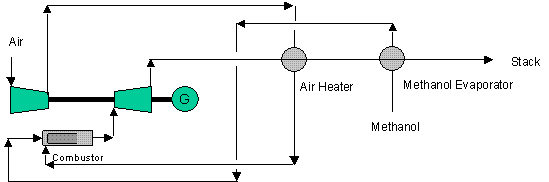
Fig.-1 Methanol Fuel Gas Turbine with Air Heating
Other way is recovering waste heat by boiler and generated steam driving steam turbine. This case is called Combined cycle. Large scale LNG fueled gas turbine cycle can achieve thermal efficiency of 59% at turbine inlet temperature of 1,500oC.
When generated steam is injected into gas turbine, it is an integration of gas turbine and steam turbine cycle into single turbine. This is called Steam Injection cycle.
Methanol Fuel Gas Turbine
In 1988, it was anticipated that methanol produced from natural gas could be used as an alternative fuel of oil. At such circumstances, I have realized that there is a forth way of recovering waste heat. That is recovering waste heat as reaction heat of steam reforming of methanol.
Methanol react with water and becomes hydrogen and carbon dioxide as follows.
CH3OH + H2O = CO2 + 3H2
This reaction is endothermic and absorbs waste heat at around 300oC. The system performance was predicted using in house process simulator called CAPES and found thermal efficiency of approx. 50% (LHV) when turbine inlet temperature is 1,100oC and compression ratio is 14. For detail, please refer to Enhancing Efficiency of Methanol Fuelled Gas Turbine, International Symposium on Alcohol Fuels, 8th Tokyo 1988/11/13-16.
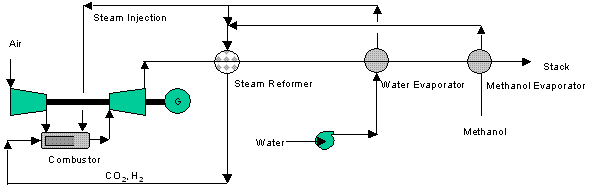
Fig.-2 Methanol Fuel Gas Turbine with Steam Reforming & Water Injection
The performance of the gas turbine with steam reforming was recalculated using PRO/II. The same adiabatic efficiency of 87% for compressor and 90% for turbine were used. Similar value of overall thermal efficiency of approx. 50% was obtained as shown in Table-1.
For reference, the performance of air heating system was also investigated. In this case, thermal efficiency was in the same level as reforming but total heat transfer area is 1.7 times of steam reforming case.
Let's explain model making of steam reformer by PRO/II. After defining stoichiometric data for steam reforming reaction, Gibbs reactor was used for equilibrium calculation at specified temperature. For combustor design, two combustion reactions were defined. Namely, methanol and hydrogen reacting with oxygen. Then two conversion reactors were connected in series and set the conversion parameter to 1. Both reactors are defined as adiabatic.>
Heat exchangers having phase change were split into 10 to 20 zones and flow configuration were set to true counter flow. Minimum pinch point were set to 10 to 20 oC. Pressure drop of each exchangers were set to 0.02-0.01 atm and overall heat transfer coefficient were set to100kcal/h C.
|
Flow Scheme |
unit |
Fig-1 |
Fig.-2 |
|
Waste Heat Recovery |
Air Heating & Methanol Evap. |
Steam Reforming, Water Injection & Methanol Evap. |
|
|
Turbine Inlet Temperature |
oC |
1,100 |
1,100 |
|
Compression Ratio |
- |
14 |
14 |
|
Methanol Rate |
kgmol/h |
0.133 |
0.133 |
|
Stoichiometric Air Rate |
kgmol/h |
1 |
1 |
|
Air Rate |
kgmol/h |
4.150 |
2.600 |
|
Reforming Water Rate |
kgmol/h |
- |
0.133 |
|
Total Water Rate |
kgmol/h |
- |
0.720 |
|
Excess Air Mol Ratio |
- |
4.150 |
2.600 |
|
Water/Air Mol Ratio |
- |
0.000 |
0.277 |
|
Water/Methanol Mol Ratio |
- |
0.000 |
5.414 |
|
1st Compressor Power |
kW |
-12.472 |
-7.814 |
|
1st Turbine Power |
kW |
24.128 |
19.750 |
|
Water Injection Pump |
kW |
- |
-0.006 |
|
Net Shaft Power |
kW |
11.656 |
11.930 |
|
Power Output |
kW |
11.423 |
11.691 |
|
Methanol Heat of Combustion (HHV) |
kW |
47.149 |
23.574 |
|
Methanol HHV |
kJ/mol |
638.10 |
638.10 |
|
Overall Thermal Efficiency (HHV) |
% |
48.45 |
49.59 |
|
Compressor Adiabatic Efficiency |
% |
87 |
87 |
|
Turbine Adiabatic Efficiency |
% |
90 |
90 |
|
Generator Efficiency |
% |
98 |
98 |
|
Methanol Evaporator Area/Pinch Point |
m2/oC |
0.140/10 |
0.138/5 |
|
Methanol Reformer Area/Reaction Temp. |
m2/oC |
- |
0.201/300 |
|
Air Heater Area/Pinch Point/Max. Temp. |
m2/oC |
2.972/10/525 |
0 |
|
Water Evaporator Area/Pinch Point |
m2 |
- |
1.452/10 |
|
Total Surface Area |
m2 |
3.112 |
1.791 |
|
Exhaust Temperature |
oC |
335.3 |
102.05 |
Table-1 Methanol Fuel Gas Turbine with Steam Reforming & Water Injection or Air Heating
Ammonia Fuel Single Stage Micro Gas Turbine with Air Heating
When you consider alternative fuel from natural gas, ammonia is superior than methanol and or dimethyl-ether (DME) as it does not generate carbon dioxide. And energy shrinkage from natural gas is similar compared to that of methanol and DME.
Currently, hybrid car uses gasoline fueled reciprocating engine called Miller cycle. Thermal efficiency of Miller cycle is approx. 38%. Although large size diesel engine with turbocharger has thermal efficiency of 47%, it does not fit with hybrid car. Ammonia fuelled micro gas turbine driven hybrid car would be probable if ammonia fuelled micro gas turbine could achieve thermal efficiency above 38%.
When air bearing is used, lubrication system could be eliminated and can expect longer life even gas turbine is intermittent on/off operation.
The purpose of this study is to investigate such possibility.
Firstly, single stage compression of which compression ratio is from 3 to 4 were investigated. It is possible to compress air up to the compression ratio of 4 by single impeller. In any case, adiabatic efficiency of compressor was fixed at 80% and that of turbine was 90% throughout the study.
Regarding turbine inlet temperature, two cases were considered. Namely, 1,200oC using ceramic blade and 900oC using alloy blade.
In this study, ammonia evaporation was always considered for all cases.
Now, I have investigated air heating by turbine waste heat. The system called regenerative cycle is illustrated as Fig.-3.
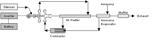
Fig.-3 Ammonia Fuel Single Stage Micro Gas Turbine with Air Heating
Results are summarized in Table-2. When turbine inlet temperature is 900oC, optimum compression ratio is around 3. This means that higher turbine exhaust temperature assures higher waste heat recovery. Naturally, higher turbine inlet temperature of 1,200oC gives highest efficiency of 39%. This means the possibility of micro gas turbine hybrid car. But it should be noted that air heater maximum temperature exceed 900oC.
|
Flow Scheme |
unit |
Fig.-3 |
Fig.-3 |
1Fig.-3 |
|
Waste Heat Recovery |
Air Heating & Ammonia Evap. |
Air Heating & Ammonia Evap. |
Air Heating & Ammonia Evap. |
|
|
Turbine Inlet Temperature |
oC |
1,200 |
900 |
900 |
|
Compression Ratio |
- |
3 |
3 |
4 |
|
Impeller Head |
m |
14,415 |
14,415 |
18,993 |
|
Impeller Diameter |
inch |
4 |
4 |
4 |
|
Rotation |
rpm |
70,669 |
70,669 |
81,118 |
|
Mach Number |
- |
0.88 |
0.88 |
0.99 |
|
Specific Speed |
rpm |
215 |
254 |
216 |
|
Ammonia Rate |
kgmol/h |
0.266 |
0.266 |
0.266 |
|
Stoichiometric Air |
kgmol/h |
1 |
1 |
1 |
|
Air Rate |
kgmol/h |
6.700 |
9.361 |
7.802 |
|
Water Rate |
kgmol/h |
0.000 |
0.000 |
0.000 |
|
Excess Air Mol Ratio |
- |
6.700 |
9.361 |
7.802 |
|
Water/Air Mol Ratio |
- |
0.000 |
0.000 |
0.000 |
|
Water Ammonia Mol Ratio |
- |
0.000 |
0.000 |
0.000 |
|
1st Compressor Power |
kW |
-7.563 |
-10.267 |
-11.209 |
|
1st Turbine Power |
kW |
18.922 |
20.113 |
20.703 |
|
Net Shaft Power |
kW |
11.359 |
9.846 |
9.494 |
|
Power Output |
kW |
11.132 |
9.649 |
9.304 |
|
Ammonia Heat of Combustion (LHV) |
kW |
28.270 |
28.270 |
28.270 |
|
Ammonia LHV |
kJ/mol |
382.60 |
382.60 |
382.60 |
|
Overall Thermal Efficiency (LHV) |
% |
39.38 |
34.13 |
32.91 |
|
Compressor Adiabatic Efficiency |
% |
80 |
80 |
80 |
|
Turbine Adiabatic Efficiency |
% |
85 |
85 |
85 |
|
Generator Efficiency |
% |
98 |
98 |
98 |
|
Ammonia Evaporator Area/Pinch Point |
m2/oC |
0.083/10 |
0.076/10 |
0.084/10 |
|
Air Heater Area/Pinch Point/Max Temp. |
m2/oC |
7.374/30/926 |
10.94/20 |
7.372/20 |
|
Total Surface Area |
m2 |
7.457 |
11.016 |
7.456 |
|
Exhaust Temperature |
oC |
236.7 |
205.1 |
243.8 |
Table-2 Ammonia Fuel Single Stage Micro Gas Turbine with Air Heating
Previous study conducted by Prof. Nobuhide Kasagi of Tokyo University showed that higher compression ratio does not improve performance. Therefore Two Stage case was not considered.
Ammonia Fuel Single Stage Micro Gas Turbine with Water Recycling
Characteristic of ammonia is hydrogen rich fuel. This means that if you burn ammonia with stoichiometric air, dew point of exhaust gas becomes 70.1oC. This is above ambient temperature and you can recover water from turbine exhaust and recycle back to the turbine after heat recovery. In this case, it is not necessary to carry water tank on the hybrid car.
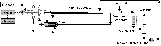
Fig.-4 Ammonia Fuel Single Stage Micro Gas Turbine with Water Recycling
I have investigated the overall thermal efficiency of turbine inlet temperature of 1,200 to 900oC and compression ratio of 3 to 4.
Results are shown in Table-3. Naturally, higher turbine inlet temperature shows better performance. Excess air improves performance but it lower water dew point of the exhaust gas and water recovery becomes difficult. In any case, the results are not promising .
|
Flow Scheme |
unit |
Fig.-4 |
Fig.-4 |
Fig.-4 |
Fig.-4 |
|
Waste Heat Recovery |
Water Recycle & Ammonia Evap. |
Water Recycle & Ammonia Evap. |
Water Recycle & Ammonia Evap. |
Water Recycle & Ammonia Evap. |
|
|
Turbine Inlet Temperature |
oC |
900 |
1,200 |
900 |
900 |
|
Compression Ratio |
- |
3 |
3 |
3 |
4 |
|
Impeller Head |
m |
14,415 |
14,415 |
14,415 |
18,993 |
|
Impeller Diameter |
inch |
4 |
4 |
4 |
4 |
|
Rotation |
rpm |
70,669 |
70,669 |
70,669 |
81,116 |
|
Mach Number |
- |
0.88 |
0.88 |
0.88 |
0.99 |
|
Specific Speed |
rpm |
113 |
84 |
84 |
79 |
|
Ammonia Rate |
kgmol/h |
0.266 |
0.266 |
0.266 |
0.266 |
|
Stoichiometric Air |
kgmol/h |
1 |
1 |
1 |
1 |
|
Air Rate |
kgmol/h |
1.800 |
1.000 |
1.000 |
1.000 |
|
Water Rate |
kgmol/h |
1.410 |
1.400 |
2.213 |
1.530 |
| Condensaer Fan Air Rate | kgmol/h |
120 |
100 |
110 |
82 |
|
Excess Air Mol Ratio |
- |
1.800 |
1.000 |
1.000 |
1.000 |
|
Water/Air Mol Ratio |
- |
0.783 |
2.213 |
2.213 |
1.530 |
|
Water Ammonia Mol Ratio |
- |
5.301 |
5.263 |
8.320 |
5.752 |
|
1st Compressor Power |
kW |
-2.032 |
-1.129 |
-1.129 |
-1.487 |
|
1st Turbine Power |
kW |
7.611 |
7.427 |
6.137 |
6.148 |
|
Water Injection Pump |
kW |
-0.002 |
-0.002 |
-0.002 |
-0.002 |
|
Condenser Fan |
kW |
-0.21 |
-0.175 |
-0.192 |
-0.143 |
|
Net Shaft Power |
kW |
5.367 |
6.121 |
4.814 |
4.516 |
|
Power Output |
kW |
5.260 |
5.999 |
4.718 |
4.426 |
|
Ammonia Heat of Combustion (LHV) |
kW |
28.270 |
28.270 |
28.270 |
28.270 |
|
Ammonia LHV |
kJ/mol |
382.60 |
382.60 |
382.60 |
382.60 |
|
Overall Thermal Efficiency (LHV) |
% |
18.61 |
21.22 |
16.69 |
15.66 |
|
Compressor Adiabatic Efficiency |
% |
80 |
80 |
80 |
80 |
|
Turbine Adiabatic Efficiency |
% |
85 |
85 |
85 |
85 |
|
Generator Efficiency |
% |
98 |
98 |
98 |
98 |
|
Ammonia Evaporator Area/Pinch Point |
m2/oC |
0.042/10 |
0.043/10 |
0.043/10 |
0.037/15 |
|
Water Evaporator Area/Pinch Point |
m2/oC |
1.803/20 |
1.453/20 |
1.504/20 |
1.202/25 |
|
Water Condenser Area |
m2 |
4.915 |
3.810 |
4.060 |
4.730 |
|
Total Surface Area |
m2 |
6.765 |
5.306 |
5.607 |
5.969 |
|
Exhaust/Condenser Fan Air Temp. |
oC |
60/48 |
70.1/50 |
70.1/50 |
70.1/58 |
Table-3 Ammonia Fuel Single Stage Micro Gas Turbine with Water Recycling
Ammonia Fuel Two Stage Micro Gas Turbine with Water Recycling
As single stage micro gas turbine is not promising, two stage micro gas turbine was investigated. The system looks like Fig.-5.
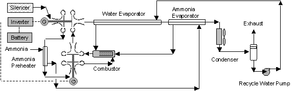
Fig.-5 Ammonia Fuel Two Stage Micro Gas Turbine with Water Recycling
In this case, compression ratio was from 12 to 16 and turbine inlet temperature was1,200 to 900oC.
The results are summarized in Table-4. The performance is better than single stage but it is inferior than air heating.
|
Flow Scheme |
unit |
Fig-5 |
Fig-5 |
Fig-5 |
Fig-5 |
|
Waste Heat Recovery |
Water Recycle & Ammonia Evap. |
Water Recycle & Ammonia Evap. |
Water Recycle & Ammonia Evap. |
Water Recycle & Ammonia Evap. |
|
|
Turbine Inlet Temperature |
oC |
900 |
900 |
900 |
1,200 |
|
Compression Ratio |
- |
12 |
14 |
16 |
16 |
|
Impeller Head |
m |
16,638+17,301 |
17,890+18,643 |
17,890+13,643 |
17,890+13,643 |
|
Impeller Diameter |
inch |
4+4 |
4+4 |
4+4 |
4+4 |
|
Rotation |
rpm |
75,923+77,420 |
78,727+80,367 |
78,727+80,367 |
78,727+80,367 |
|
Mach Number |
- |
0.95+0.94 |
0.98+0.97 |
0.98+0.97 |
0.98+0.97 |
|
Specific Speed |
rpm |
81+44 |
80+42 |
80+42 |
80+42 |
|
Ammonia Rate |
kgmol/h |
0.266 |
0.266 |
0.266 |
0.266 |
|
Stoichiometric Air |
kgmol/h |
1 |
1 |
1 |
1 |
|
Air Rate |
kgmol/h |
1.000 |
1.000 |
1.000 |
1.000 |
|
Water Rate |
kgmol/h |
2.410 |
2.350 |
2.160 |
2.160 |
|
Condenser Fan Air Rate |
kgmol/h |
80 |
58 |
80 |
80 |
|
Excess Air Mol Ratio |
- |
1.000 |
1.000 |
1.000 |
1.000 |
|
Water/Air Mol Ratio |
- |
2.410 |
2.350 |
2.160 |
2.160 |
|
Water/Ammonia Mol Ratio |
- |
9.060 |
8.835 |
8.120 |
8.120 |
|
1st Compressor Power |
kW |
-1.303 |
-1.401 |
-1.487 |
-1.487 |
|
2nd Compressor Power |
kW |
-1.355 |
-1.460 |
-1.553 |
-1.553 |
|
1st Turbine Power |
kW |
6.173 |
6.441 |
6.646 |
7.792 |
|
2nd Turbine Power |
kW |
4.730 |
4.883 |
4.981 |
5.917 |
|
Water Injection Pump |
kW |
-0.009 |
-0.010 |
-0.011 |
-0.009 |
|
Condenser Fan |
kW |
-0.140 |
-0.140 |
-0.140 |
-0.140 |
|
Net Shaft Power |
kW |
8.096 |
8.313 |
8.436 |
10.520 |
|
Power Output |
kW |
7.934 |
8.147 |
8.267 |
10.310 |
|
Ammonia Heat of Combustion (HHV) |
kW |
28.270 |
28.270 |
28.270 |
28.270 |
|
Ammonia HHV |
kJ/mol |
382.60 |
382.60 |
382.60 |
382.60 |
|
Overall Thermal Efficiency (HHV) |
% |
28.07 |
28.82 |
29.24 |
36.47 |
|
Compressor Adiabatic Efficiency |
% |
80 |
80 |
80 |
80 |
|
Turbine Adiabatic Efficiency |
% |
85 |
85 |
85 |
85 |
|
Generator Efficiency |
% |
98 |
98 |
98 |
98 |
|
Ammonia Preheater Area/Pinch Point |
m2/oC |
0.200/10 |
0.234/10 |
0.261/10 |
0.261/10 |
|
Ammonia Evaporator Area/Pinch Point |
m2/oC |
0.090/10 |
0.079/10 |
0.067/10 |
0.072/10 |
|
Water Evaporator Area/Pinch Point |
m2/oC |
1.527/20 |
1.579/20 |
1.612/20 |
1.505/20 |
|
Water Condenser Area/Pinch Point |
m2 |
3.063 |
2.998 |
2.979 |
2.401 |
|
Total Surface Area |
m2 |
4.880 |
4.890 |
4.919 |
4.239 |
|
Exhaust/Condenser fan Air Temp. |
oC |
70.1/50 |
70.1/58 |
70.1/50 |
70.1/47 |
Table-4 Ammonia Fuel Two Stage Micro Gas Turbine with Water Recycle
Ammonia Fuel Two Stage Micro Gas Turbine with Decomposition and Water Recycling
Like methanol, ammonia could catalytically decomposes at the temperature above 320oC.
2NH3 = N2 + 3H2
This reaction is endothermic and absorbs waste heat.
Similarly to methanol, ammonia fuel two stage micro gas turbine with decomposition & water recycling system could be configured as shown in Fig.-6.
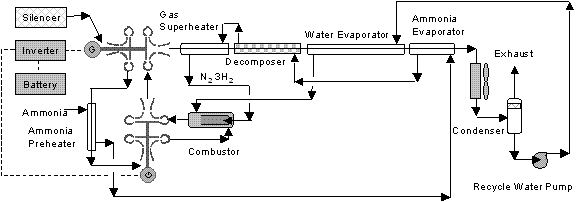
Fig.-6 Ammonia Fuel Two Stage Micro Gas Turbine with Decomposition & Water Recycling
In this case, compression ratio was fixed at 14 and turbine inlet temperature was1,200 to 900oC.
Decomposer model was Gibbs reactor and isothermal reaction was assumed. Similarly to methanol case, hypothetical two conversion type reactors installed in series are used for combustor.
The results are summarized in Table-5. When turbine inlet temperature is 1,200oC, the performance is almost same as air heating case, but total heat transfer area is a bit smaller. When turbine inlet temperature is 900oC, thermal efficiency is inferior than air heating.
|
Flow Scheme |
unit |
Fig-6 |
Fig-6 |
|
Waste Heat Recovery |
Decomposition, Water Recycle & Ammonia Evap. |
Decomposition, Water Recycle & Ammonia Evap. |
|
|
Turbine Inlet Temperature |
oC |
1,200 |
900 |
|
Compression Ratio |
- |
14 |
14 |
|
Impeller Head |
m |
17,890+18,644 |
17,890+18,644 |
|
Impeller Diameter |
inch |
4+4 |
4+4 |
|
Rotation |
rpm |
78,727+80,369 |
78,727+80,369 |
|
Mach Number |
- |
0.97+0.98 |
0.97+0.98 |
|
Specific Speed |
rpm |
89+42 |
89+42 |
|
Ammonia Rate |
kgmol/h |
0.266 |
0.266 |
|
Stoichiometric Air |
kgmol/h |
1.000 |
1.000 |
|
Air Rate |
kgmol/h |
1.000 |
1.000 |
|
Water Rate |
kgmol/h |
1.075 |
1.124 |
|
Condenser Fan Air Rate |
kgmol/h |
80 |
80 |
|
Excess Air Mol Ratio |
- |
1.000 |
1.000 |
|
Water/Air Mol Ratio |
- |
1.075 |
1.124 |
|
Water/Ammonia Mol Ratio |
- |
4.041 |
4.226 |
|
1st Compressor Power |
kW |
-1.401 |
-1.401 |
|
2nd Compressor Power |
kW |
-1.460 |
-1.460 |
|
1st Turbine Power |
kW |
8.046 |
6.478 |
|
2nd Turbine Power |
kW |
6.066 |
4.845 |
|
Water Injection Pump |
kW |
-0.010 |
-0.010 |
|
Condenser Fan |
kW |
-0.140 |
-0.140 |
|
Net Shaft Power |
kW |
11.101 |
8.312 |
|
Power Output |
kW |
10.879 |
8.146 |
|
Ammonia Heat of Combustion (HHV) |
kW |
28.270 |
28.270 |
|
Ammonia HHV |
kJ/mol |
382.60 |
382.60 |
|
Overall Thermal Efficiency (HHV) |
% |
38.48 |
28.81 |
|
Compressor Adiabatic Efficiency |
% |
80 |
80 |
|
Turbine Adiabatic Efficiency |
% |
85 |
85 |
|
Generator Efficiency |
% |
98 |
98 |
|
Ammonia Preheater Area/Pinch Point |
m2/oC |
0.234/10 |
0.234/10 |
|
Ammonia Evaporator Area/Pinch Point |
m2/oC |
0.079/10 |
0.076/10 |
|
Ammonia Superheater Area/Pinch Point |
m2/oC |
0.125/10 |
0.102/10 |
|
Decomposition Reactor Area/Reaction Temp |
m2/oC |
0.292/500 |
0.831/320 |
| Gas Superheater Area/Pinch Point |
m2/oC |
0.127/20 |
0 |
|
Water Evaporator Area/Pinch Point |
m2/oC |
1.574/10 |
2.384/10 |
|
Water Condenser |
m2 |
2.903 |
3.004 |
|
Total Surface Area |
m2 |
5.334 |
5.800 |
|
Exhaust/Condenser Fan Air Temp. |
oC |
70.1/50 |
70.1/50 |
Table-5 Ammonia Fuel Two Stage Micro Gas Turbine with Decomposition & Water Recycling
Ammonia Fuel Two Stage Micro Gas Turbine with Cascade & Water Recycling
Stirling Cycle cycle is equivalent to externally heated gas turbine cycle. This cycle was adopted as bottoming cycle for two stage micro gas turbine as illustrated in Fig.-7.
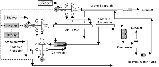
Fig.-7 Ammonia Fuel Two Stage Micro Gas Turbine with Cascade & Water Recycling
The simulation results is shown in Table-6. The performance was not superior than others.
|
Flow Scheme |
unit |
Fig-7 |
|
Waste Heat Recovery |
Cascade, Water Recycle & Ammonia Evap. |
|
|
Turbine Inlet Temperature |
oC |
900 |
|
Compression Ratio |
- |
14 + 3 |
|
Impeller Head |
m |
17,887+18,642+14,568 |
|
Impeller Diameter |
inch |
4+4+4 |
|
Rotation |
rpm |
78,721+80,367+71,043 |
|
Mach Number |
- |
0.97+0.97+0.90 |
|
Specific Speed |
rpm |
80+42+122 |
|
Ammonia Rate |
kgmol/h |
0.266 |
|
Stoichiometric Air |
kgmol/h |
1 |
|
Air Rate |
kgmol/h |
1 + 2.1 |
|
Water Rate |
kgmol/h |
0.720 |
|
Condenser Fan Air Rate |
kgmol/h |
75 |
|
Excess Air Mol Ratio |
- |
1.000 |
|
Water/Air Mol Ratio |
- |
0.720 |
|
Water/Ammonia Mol Ratio |
- |
2.707 |
|
1st Compressor Power |
kW |
-1.401 |
|
2nd Compressor Power |
kW |
-1.460 |
|
3rd Compressor Power |
kW |
-2.396 |
|
1st Turbine Power |
kW |
5.862 |
|
2nd Turbine Power |
kW |
4.432 |
|
3rd Turbine Power |
kW |
2.701 |
|
Water Injection Pump |
kW |
-0.008 |
|
Condenser Fan |
kW |
-0.131 |
|
Net Shaft Power |
kW |
7.599 |
|
Power Output |
kW |
7.447 |
|
Ammonia Heat of Combustion (HHV) |
kW |
28.270 |
|
Ammonia HHV |
kJ/mol |
382.60 |
|
Overall Thermal Efficiency (HHV) |
% |
26.34 |
|
Compressor Adiabatic Efficiency |
% |
80 |
|
Turbine Adiabatic Efficiency |
% |
85 |
|
Generator Efficiency |
% |
98 |
|
Ammonia Preheater Area/Pinch Point |
m2/oC |
0.234/10 |
|
Ammonia Evaporator Area/Pinch Point |
m2/oC |
0.099/10 |
|
Air Heater Area/Pinch Point |
m2/oC |
1.105/20 |
|
Water Evaporator Area/Pinch Point |
m2/oC |
1.563/10 |
|
Water Condenser |
m2 |
1.497 |
|
Total Surface Area |
m2 |
4.498 |
|
Exhaust/Condenser Fan Air Temp. |
oC |
70.1/51 + 80.26 |
Table-6 Ammonia Fuel Two Stage Micro Gas Turbine with Cascade & Water Recycling
Point of Model Making
Condenser has pint point. therefore, heat exchanger has to be split into 20 zones and specify minimum internal temperature approach. Also check shape of condensing and evaporating by Hcurve in Tool menu.
Conclusions
When turbine inlet temperature is 1,200oC, both air heating and decomposition plus water injection gives similar thermal efficiency around 39%, but when turbine inlet temperature is 900oC, air heating gives better thermal efficiency around 34%.
In any case, water injection gives smaller heat transfer area than air heating.
Acknowledgment
Author is grateful to Invensys Systems Japan, Inc. for letting author to use PRO/II.
December 24, 2009
Rev. August 21, 2011