The drive force has been changed from electric field force to image force.
New information.
Some responses to this new electrostatic generator happened from the last summer to this spring. Contents
1: Asymmetric image force.
China two times invited me to China with high salary and high research money.
However, I refused because today the relationship between China and Japan was not good.
Many companies in Japan that develop a new useful machine can get research money from NEDO.
One chief of NEDO sent me an email that your electrostatic generator laboratory can get research money from NEDO.
However, I could not because electrostatic generator laboratory was personal research house.
I sent my research plan of the new electrostatic generator to NIKKEI non-carbon award, however It was not accepted because the plan was not perfect.
My friend made a hybrid research team consisted of OB and active researcher of the same one company.
They made an improved experimental equipment of the new electrostatic generator.
As a result, we could get many important data that were very useful for commercial machine product.
Therefore, this became a formal research subject of the company from this April.
As a result, I canÅft rewrite this home page with new data of the improved experimental equipment until the company allow me to do.
Therefore, I will freeze this home page for some time.
2: Principle of asymmetric image force driven electrostatic generation
3: The first experimental equipment of the asymmetric image force driven electrostatic generator.
4: The defect of the first equipment and the design of the second equipment that improved the defect.
5: The method that can increase the electric output largely.
6: The expected commercial electric machine and its development plan.
Supplementary note
Features of the new electrostatic generator
Application fields of the new electrostatic generator
Papers and Books.
Patents.
Today, many electric generating methods that don't produce carbon dioxide are used in the world.
For example, nuclear power generation, photovoltaic power generation, wind power generation, geothermal power generation, and the like.
However, these have drawbacks in terms of safety, stability, cost, durability, miniaturization, and the like.
On the other hand, electrostatic generators are safe throughout manufacture, use, and disposal, and their power output is always stable regardless of the weather or time of power generation.
Furthermore, since it can be easily miniaturized, storage batteries and transmission lines are not required.
Furthermore, replenishment of energy and maintenance are almost unnecessary, it is a low cost power source with a long life (approximately 100 years).
Such an electrostatic generator injects a charge into a charge carrier at a low potential charge injection electrode (hereinafter referred to as the injection electrode),
then the charge carrier is transferred to a high potential charge collection electrode (hereinafter referred to as a collection electrode), against the electrostatic force acting on the charge carrier in the transfer course.
Finaly, the transported charge is collected to the collection electrode.
However, the Van de Graaf electrostatic generator uses mechanical force (an electric motor) to transport the charge carriers against the electrostatic force, and the power consumed by the electric motor is larger than the power produced. Therefore,it is a high-potential (1 million volts) producter, but not a electric generator.
On the other hand, there is an electrostatic power generation method which uses an asymmetric image force as a driving force to pull up a charge carrier from a low potential to a high potential. The asymmetric image force has been discovered by the author in recent years.
This method will be briefly explained below.
As shown in FIG. 1, when a point charge 1 is at a distance r from a grounded conductive flat plate 2, the point charge 1 is subjected to an image force calculated by the following equation.
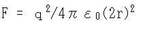
The charge is explained as a point charge or a spherically charged body, but a non-spherical charged body also generates an image force.
Here, if the charged body has a symmetrical shape, even if the direction of the charged body is reversed, the intensity of the image force acting on the charged body does not change.
However, it has been confirmed by simulations and experiments that the intensity of the image force acting on the charged body varies greatly when the charged body has an asymmetrical shape.
This phenomenon is hereinafter referred to as asymmetric image force.
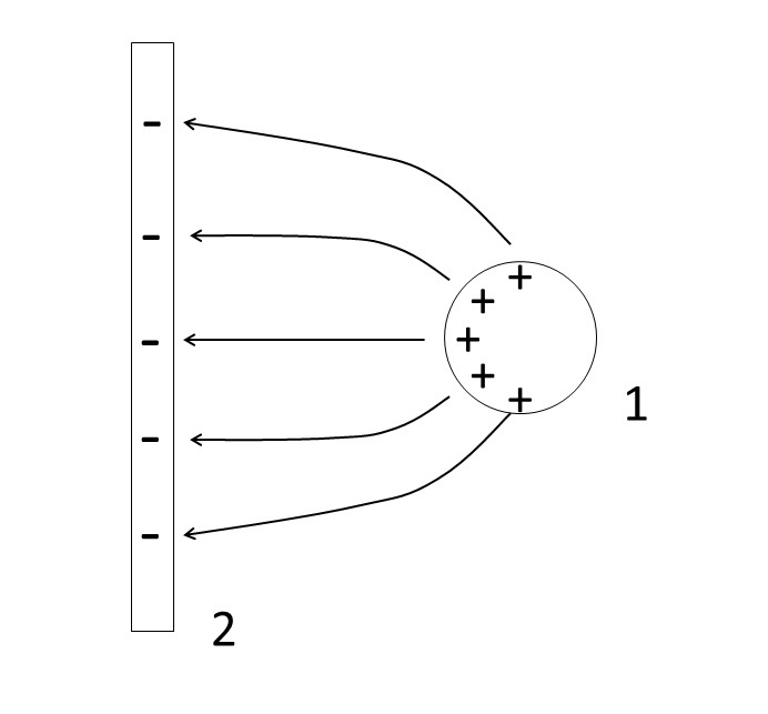
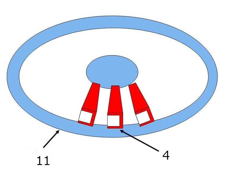
For example, it was clarified by a simulation of the two-dimensional finite difference method that when the gutter-type charge carrier 4 shown in FIG. 2 has a charge amount of 1 É C, and the distance from the grounded conductor plate 2 is 1.0 mm,
When the opening is directed toward the ground conductor plate 2, the image force acting on the charge carrier 4 is 32.4N,
Conversely,when the bottom surface faces the ground conductor plate 2, the image force becomes 69.0N.
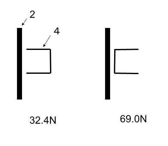
FIG. 3 shows the basic structure of an electrostatic generator that uses this asymmetric image force as a driving force for the charge carrier.
However, in an actual device, a collection electrode capacitor 6, a conductive terminal 7 for injecting charge, and a conductive terminal 8 for collecting charge are added.
For the sake of simplification, only main parts will be mainly described below.
When the charge carrier 4 enters between a pair of upper and lower injection electrodes (e.g., electrets) 3 from the left in FIG. 3 and reaches the position shown in FIG.3
Air capacitors are formed between the upper and lower side plates 42 of the charge carrier 4 and the pair of upper and lower injection electrode 3, respectively.
At this time, when the charge carrier 4 is grounded by the charge injection terminal 7, the charged charge in the air capacitor is injected into the charge carrier 4 from the ground.
After that, the charged charge carrier 4 moves further to the right and enters the pair of upper and lower collection electrodes 5.
The collection electrode 5 and the charge carrier 4 are electrically connected to each other by a charge collection terminal 8.
At this time, the charge is collected by the collection electrode 5 according to the principle of the Faraday gauge.
Then the collected charges are accumulated in the collection electrode capacitor 6.
Then, the charged charges flow to the external load through a circuit (not shown).
When polarity of the injection electret 3 is negative, the charge carrier 4 is positively charged.
As a result, the electric field formed between the injection electret 3 and the collection electrode 5 causes a leftward electrostatic force to act on the charge carrier 4 traveling to the right between the injection electret 3 and the collection electrode 5 .
This force is hereinafter referred to as the backward electric field force.
In addition, a leftward image force occurs between the back electrode of the injection electret 3 and the charge carrier 4 .
This force is hereinafter referred to as the backward image force.From now on, electric field force will be abbreviated as EF force.
At the same time, a rightward image force occurs between the collection electrode 5 and the charge carrier 4.
This force is hereinafter referred to as forward image force.
Here, when the charge carrier 4 is asymmetric, the resultant force of the backward electric field force and the backward image force is strong immediately after leaving the injection electret 3.
However, when approaching the collection electrode 5, the rightward (positive) forward image force becomes stronger.
FIG. 4 shows the result of simulating the electrostatic force acting on the charge carrier 4 of the first experimental device shown below by the two-dimensional finite difference method.
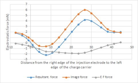
In the figure, the red line indicates the electrostatic force in the absence of an electric field, namely the image force, the blue line indicates the electrostatic force including the image force and the EF force, and the gray line indicates the difference between the electrostatic force and the image force, namely Indicates the EF force.
The horizontal axis indicates the distance from the left edge of the charge carrier to the right edge of the injection electrode.
That is, the simulation was performed from the charge carrier 4 was charged by the injection electrode 3 to the charge was collected by the colection electrode 5 .
From this graph it can be seen that the image force acting on the charge carrier 4 is rightward (positive) within the injection electrode, but is reversed leftward (negative) after leaving the injection electrode.
However, it can be seen that when the charge carrier is further advanced by 10 mm, the image force reverses again to the right (positive) and becomes stronger as it approaches the collection electrode. And it becomes weak when it enters the collection electrode.
On the other hand, it can be seen that the EF force (negative) is almost constant between the injection electrode and the collection electrode.
As a result, the electrostatic force, which is the resultant force of both, drops to -2mN at first, but it reverses halfway and reaches 4mN, which is double.
As a result, the charge carrier 4 can reach the collection electrode 5 from the injection electret 3 .
At this time, 62.73 É J of kinetic energy remains in the charge carrier that has reached the collection electrode.
Since the charge amount at the injection voltage +7.0 kV is -14.8 nC, the electrons transported from the low potential (0 V) can be raised to a higher potential (-2200 V).
In fact, based on this principle, an asymmetric image force-driven experimental electrostatic generator (hereinafter referred to as the first experimental machine) was prototyped and generated electricity.
Fig. 5 shows an elevation view of the first experimental machine, Fig. 6 shows a plan view, and Fig. 7 shows a photograph of the main part.
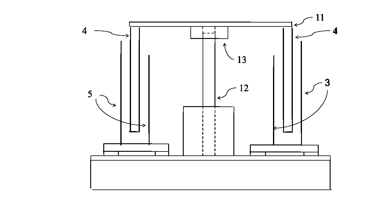
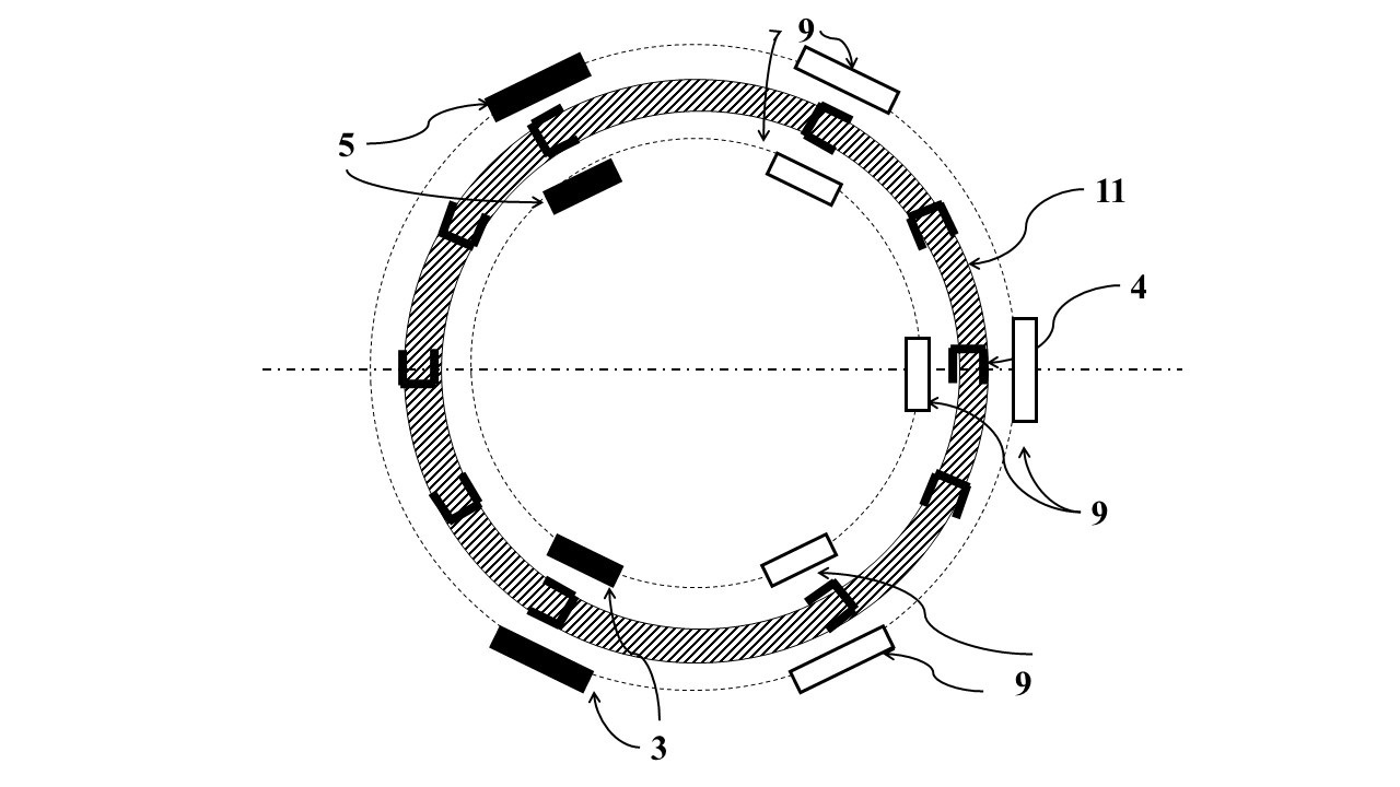
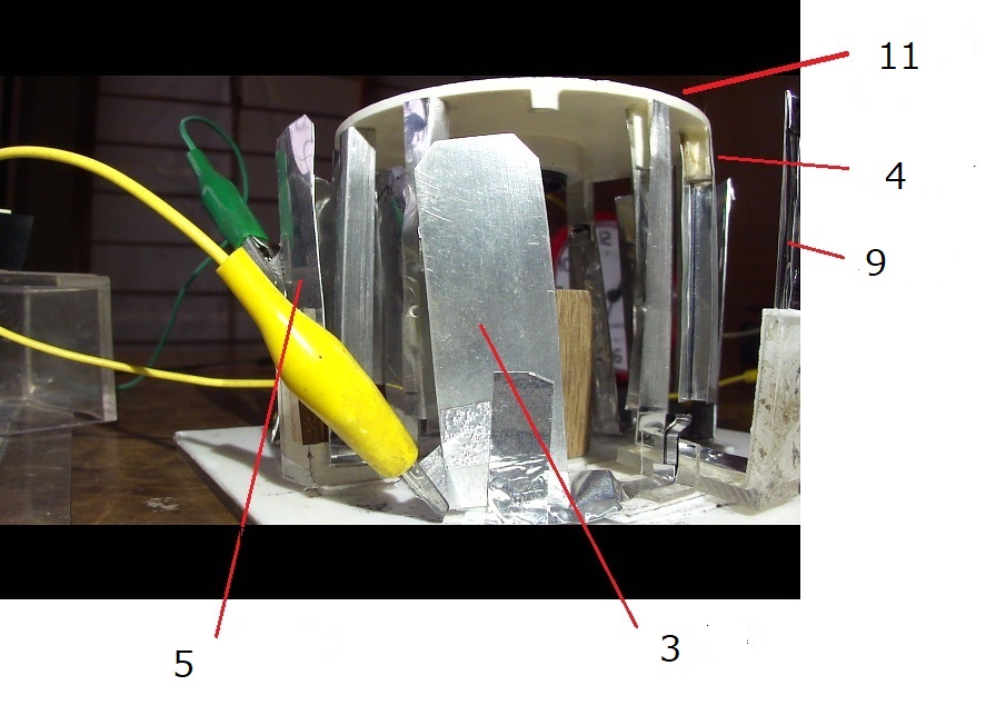
In the figure, reference numeral 4 is a gutter-shaped charge carrier, 3 is a injection electrode (electret), 5 is a collection electrode, and 9 is an acceleration electrode for enhancing the asymmetric image force, which is grounded.
Reference number 11 is a charge carrier disk that holds the charge carrier, and reference number 12 is a rotating shaft (support) made of stainless steel.
Reference number 13 is a high performance ball bearing fixed in the center of the charge carrier disc 11 and rotating about a fixed axis of rotation 12 .
Injection electric terminals and collection electric terminals are omitted.
In the experiment, a high voltage was applied to the charge electrode 3, and the charge carrier 4 was forcibly rotated counterclockwise by air spray for 3 to 30 seconds.
When passing through the injection electrodes, the charge carrier is charged and passes between the grounded acceleration electrodes, reaches the collection electrode, and releases the carried charge there.
At this time, if the electrostatic force applied to the charge carrier is greater than the resultant force of the air resistance force and the mechanical friction force applied to the charge carrier, the charge carrier disk 11 continues to rotate.
The charge injected by the injection electrode 3 continues to be collected by the collection electrode 5, and as a result, the surface potential of the collection capacitor 6 continues to rise strongly.
This result means that an electric power generation continues.
When the voltage applied to the injection electrode 3 was increased by -0.5 kV from -3.0 kV, forced rotation did not change to continuous rotation up to -5.0 kV, and stopped after several tens of seconds.
However, at -5.5kV, it continues to rotate smoothly and the potential of the collection capacitor 6 continued to rise.
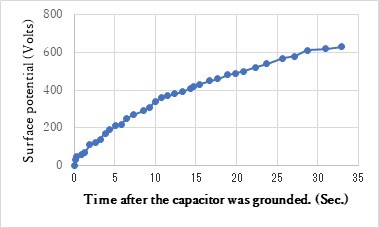
At this time, the collection capacitor 6 was grounded three times, and each time the potential rose from 0V to +600V or more.
This video can be seen below.
https://www.youtube.com/watch?v=v_nx9pVKLsc
FIG. 8 shows changes in the surface potential of the collection electrode capacitor after grounding at this time.
Since the capacitance of the capacitor is 1100pF, the current was calculated from the rising slope of the potential, and the injected charge amount was calculated from the current, it became -2.6nC.
The simulation result under the same conditions became -5.2 nC.
The amount of electric charge in the experiment was half that of the simulation, but in any case, this experimental machine succeeded in generating electricity.
This result proves the correctness of the new power generation method in which the asymmetric image force is used as the driving force of the charge carrier.
However, it is industrially meaningless to use a injection electrode that consumes electric power to charge the charge carrier by electrostatic induction.
Charging must be done with an electret that does not consume electric power.
To do so, the -5.5 kV applied injection electrode must be replaced by an electret with a surface potential of -5.5 kV.
I started making a -5.5 kV electret, but unexpectedly, I couldn't finish it even after a year and a half.
I could make a large area high potential electret.
However, when the width was reduced to 5 mm, the potential decreased.
Therefore, I asked a specialized manufacturer of electrets to manufacture it.
However, the surface potential of the fabricated electret was -3.5 kV or less.
Therefore, at the charging voltage of -3.5 kV, the charge carrier must be charged with the same amount of charge as the charging voltage of -5.5 kV.
This can be achieved by halving the gap between the charging electrode 3 and the side plate 42 of the charge carrier 4, which forms an air capacitor during charging (hereinafter referred to as the charging gap).
In the first experimental machine, the distance between the inner and outer injection electrodes is 20 mm, and the width of the charge carrier running between them is 5 mm.
Therefore, the charging gap is 7.5mm.
It seems that it can be easily halved to 3.75mm, but in reality it is not possible.
This point is the main problem of the first experimental machine.
In addition, it is also a problem that the charge amount of the actual device is only half of that of the simulation.
The reason for this is thought to be that the charge injection rate and charge collection rate were not 100% but about 70%.
This problem will be solved by improving the injection terminal and the collection terminal.
In the hand-made first experimental machine, a 60 mm long charge carrier 4 is suspended from the upper charge carrier disk 11.
Therefore, when the charge carrier disk 11 rotates at high speed, centrifugal force causes the lower end of the charge carrier 4 to spread outward and approach the injection electrode 3.
As a result, a discharge occurs between them.
In the experimental video mentioned above, you can also hear the discharge sound during high-speed rotation.
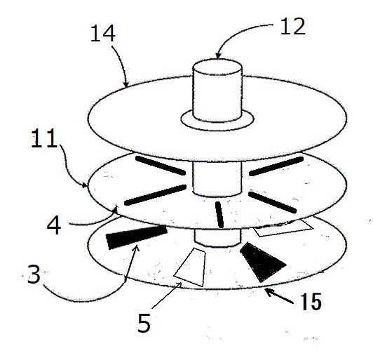
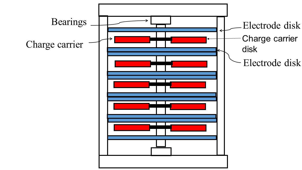
Therefore, in the second experimental machine currently being prototyped, the charge carrier 4 is placed horizontally as shown in FIG 9.
Then, as shown in FIG. 10, the charge carrier disk 11 is sandwiched between upper and lower fixed electrode plates 14 and 15 having injection electrodes 3 and collection electrodes 5.
As a result, the charging gap was reduced from 7.5mm to 1.0mm.
In addition, since the large effect of the ground acceleration electrode 9 could not be confirmed in the simulation, it was removed.
In the experimental machine, when -3.5 kV is applied to the injection electrode, it is expected that the charge carrier disk will continue to rotate and the potential of the capacitor of the collection electrode will rise continuously.
This result means that this equipment is generating electric power continuously.
After that, attach a -3.5 kV electret to the grounded injection electrode and confirm that power generation continues over a long period of time.
As part of that, although not mentioned above, it is necessary to confirm whether the electrode arrangement of the second experimental equipment is optimal.
At present, I am simulating the image force acting on the charged charge carrier by arranging the injection electrode 3, the charge carrier 4, and the collection electrode 5 in a straight line using a self-made two-dimensional finite difference method.
However, in reality, these three parts are arranged on a circle.
Therefore, the two-dimensional optimum result is not always the optimum three-dimensional arrangement in the actual machine.
Therefore, first, the optimal arrangement that maximizes the electric output is obtained using a three-dimensional electrical simulation program.
If the result is different from the current situation (electrode arrangement of the second experimental machine), change the electrode arrangement of the upper and lower electrode plates based on the three-dimensional result.
This is called the improved second experimental machine.
Perform the same experiment with this experimental machine and check the electric output.
This improved electrode arrangement will be used in the following third experimental machine.
Even if it becomes possible to charge with an electret that does not consume electric power, and the difference in the amount of charge compared to the simulation is improved, it is not yet at the stage where it can be used industrially.
High electric output is essential.
Simulations have shown that high electric output can be achieved by downsizing components such as charge carriers, injection electrets, and collection electrodes.
First, the principle will be explained with reference to FIG.11.
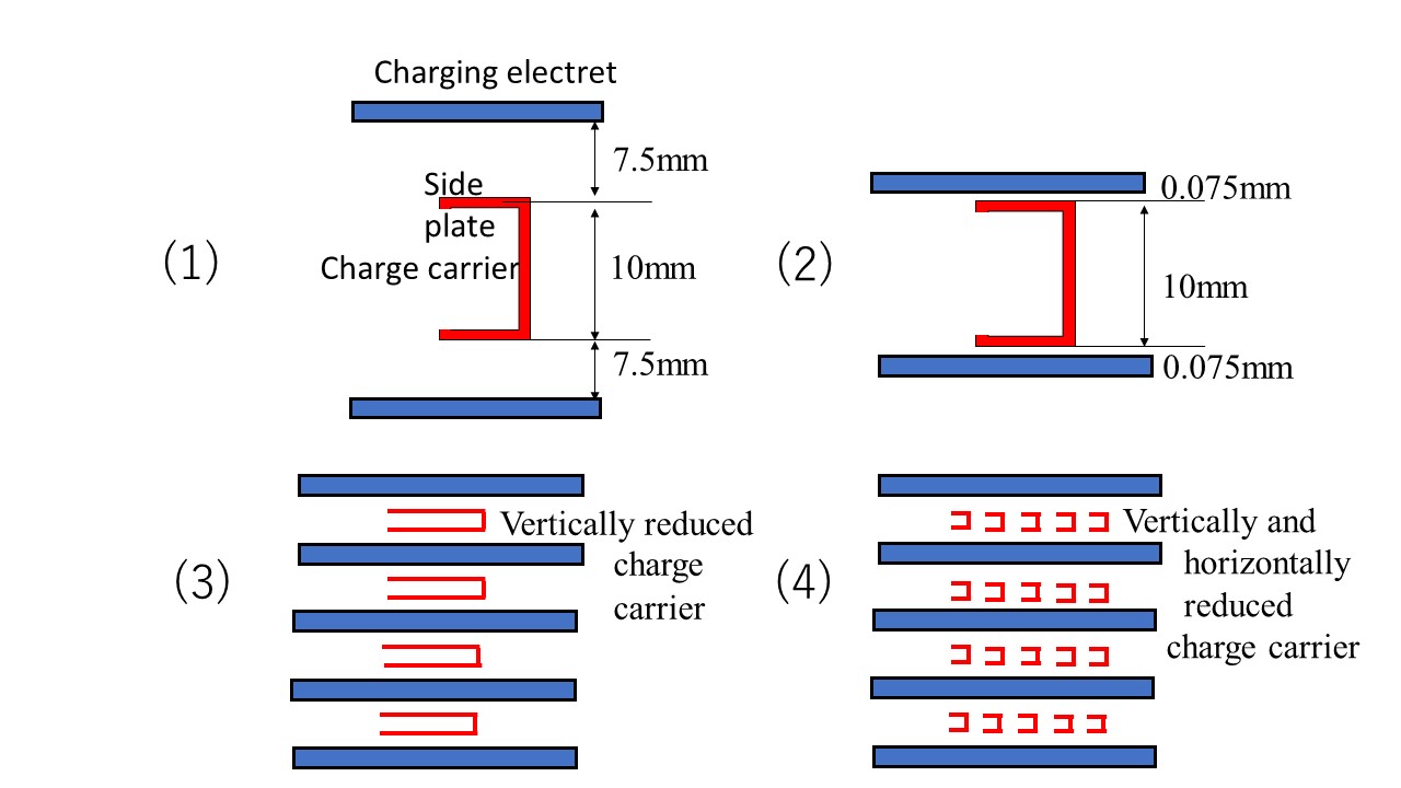
In the case of the first experimental equipment, (1) the thickness (charging gap) of the air capacitor temporarily formed by the high-potential injection electrode 3 and the side plate 42 of the grounded charge carrier 4 was 7.5 mm.
(2) If this gap is reduced to 0.075 mm, which is 1/100, the charged charge density of the charge carrier 4 will increase 100 times.
In this case, the charged charge density is independent of the height of the charge carrier 4 .
(3) Therefore, even if the height of the charge carrier 4 is reduced to 0.1 mm, which is 1/100, the charged charge density does not change.
However, since the height is reduced to 1/100, it becomes possible to stack 100 charge carriers 4 .
That is, the amount of charge in the same volume becomes 100 times.
(4) However, if the height of the charge carrier is reduced to 0.1 mm, but the length of the side plate is 10 mm same, the electrostatic force applied to 0.1 mm height cannot pull the charge carrrier that has 10mm side plates.
Therefore, it is necessary to reduce the length of the side plate to 1/100.
Since the charge amount of one charge carrier is increased 100 times and 100 charge carriers are stacked in the same volume, the charge amount of the same volume is increased 10,000 times.
Furthermore, if the amount of charge increases 100 times, the electrostatic force also increases 100 times or more, and the rotational speed of the charge carrier disk 11 is expected to increase from 100 rpm to 10,000 rpm.
Since the electric output is the amount of charge transported multiplied by the transport speed, combining these results should multiply the electric output by a factor of 1,000,000.
Not only downsizing but also increasing the charge amount of the charge carrier is effective for increasing the electric output.
No, this one is more effective.
This is because the image force is proportional to the square of the electric charge.
I simulated the electrostatic force acting on a charge carrier with a width and height of 1.0 mm and a thickness of 0.04 mm when the charge amounts were -1.0 nC and -24.0 nC.
A charge carrier charge of 24.0 nC can now be achieved by using the electret with the highest charge density (-2.0 mC/m2) as the injection electret.
FIG. 12 shows the simulation results.
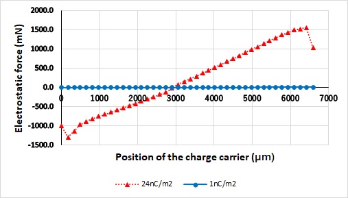
The electrostatic force acting on -24nC became 480 times the electrostatic force acting on -1nC.
As a result, the extra energy also increased significantly, and the charge of -24nC can be increased to over 50000V.
At a charge of -24 nC, there is enough extra energy to rotate the charge carrier disc at 10,000 rpm.
As a result, the current becomes 3.9mA, and the electric output of the one set that consists of the charge carrier disk and the upper and lower electrode plates becomes 194W.
If 57 sets are stacked in a 10 cm cube, the electric output will be 11 kW, which is enough to supply electricity for 2-3 houses.
However, a device that converts DC 50,000V to AC 100V cannot be placed in the home.
So, for example, put 1000 10 cm cubes generator into 1 cubic meter box and make a distributed mini power plant of 11000 kW,
And at that converting the voltage from DC 50,000V to AC 100V and transmitting it to 2,500 households, for example, high-rise condominiums, is acceptable.
In addition, it is expected that the non-electrified areas, which are currently said to have 1 billion to 2 billion people, can be solved by this method.
It should be noted that installation in an electric vehicle is also considered based on the electrical output per unit volume of the device.
In addition, it can be expected to be installed on large ships and large aircraft.
On the other hand, most of the extra energy is wasted, but if you take out the DC 400V, you can convert it to AC 400V with a transistor converter and lower it to AC 100V with a transistor transformer.
The electric output of this one set is 1.55W, so if you stack 57 sets on a 10cm cube box , the electric output becomes 88W.
It is fully usable as a portable external power supply for PCs.
In addition, since 10*10*2cm generator has an electric output of 17W, it can be incorporated into a low-power PC.
An external power supply for smartphones is also fully possible, but further miniaturization is required to incorporate it inside.
It is still difficult with the current technology to downsize the height of the charge carrier to 0.1 mm.
Therefore, as a first step, a charge carrier with a height of 1 mm and a width of 1 mm is planned.
A set of upper and lower electrode plates and charge carrier disc that has this charge carrier is called a third experimental machine.
There are several ideas for how to fabricate the charge carrier with a height of 1 mm.
However, considering further miniaturization in the future, it is thought that it is better to fabricate with PCB rather than fabricate mechanically.
The details will be announced after filing the patent application.
Although the third experimental machine has more charge carriers than the second experimental machine, they have the same total area of the side plate of the charge carrier, so the third becoms thinner, but the electric output is the same.
Therefore, in order to increase the output, it is necessary to stack thin charge carriers in multiple stages.
However, it is difficult to suddenly stack tens or hundreds of sets, so first, as shown in Fig. 13, we create a five-sets layered experimental machine (called the fourth experimental machine) and confirme that the electric output increased five times.
We will execute from the above mentioned three-dimensional electrical simulation to the fourth experimental machine , in one year from April 2023.
if possible, it will be done cooperating with JAXA.
1. No maintenance or energy supply required (in the case of magnetic levitation rotation, lubrication is required for bearings).
2. Does not generate CO2.
3, Miniaturization is possible.
4. The parts required for manufacturing are common and the product cost is low.
5. Long life (the life of the electret is 100 years).
6. The output is stable.
7, No danger (during manufacturing, use, disposal)
8. Lightweight.
9. Directly connected power supply for each electric product, eliminating the need for power transmission lines and capacitors.
ÅE Elimination of non-electric areas, temporary power supply in disaster areas, power supply in nuclear shelters.
ÅE Use in space where sunlight does not reach (beyond Jupiter).
ÅE Use inside the body where energy cannot be supplied from the outside, such as an artificial heart.
ÅE Electronic devices that need to be charged frequently, such as smartphones and PCs.
ÅE Power supply for radiotelephone relay stations. It can be installed on telephone poles without the need for solar cells or storage batteries.
ÅE Power supply for equipment (traffic signals, emergency guidance) required even during a power outage.
ÅE Power supply for meteorological observation equipment that is difficult to replace batteries in the sea, in tunnels, on mountain peaks, etc. And so on.
1. K. Sakai, Electrostatic power generating method with using image force, Proc. ESA/IEJ/IEEE-IAS/SFE Joint Conference on Electrostatics 2006 137-146.
2. K. Sakai, ÅgA symmetric conductor in convergent field vs. an asymmetric conductor in parallel fieldÅh, Proceedings of 2007 ESA annual Conference p.155
3. K. Sakai, ÅgAn experimental result which confirms the fourth electrostatic forceÅh Proceedings of 2008 ESA annual Conference D3
4. K. Sakai, ÅgThe electrostatic force that acts on the charged asymmetric conductor in a high electric field,Åh Proceedings of 2009 Electrostatics Joint Conference (2009) P2.07
5. K. Sakai, "An overlooked electrostatic force that acts on a non-charged asymmetric conductor in a symmetric (parallel) electric field ", Journal of Electrostatics Vol.67 Issue 1 (2009) pp.67-pp.72
6. K. Sakai, ÅgElectrostatic force that acts on non- sphere shape charged conductorsÅh, Proceedings of 2010 ESA annual Conference (2010) G4
7. K. Sakai, et al., Electrostatics: Theory and Applications, first ed. Nova Science Publish, New York, 2010 (Chapter 1)
8. K. Sakai, Asymmetric Electrostatic Forces and a New Electrostatic Generator, first ed. Nova Science Publish, New York, 2010
9. K. Sakai, ÅgA simple experiment result that confirmed asymmetric electrostatic forceÅh, Proceedings of 2011 ESA annual Conference (2011) B4
10. K. Sakai, ÅgWhat is the energy of an electric field?Åh Proceedings of 2012 Electrostatics Joint Conference (2012) PS13
11. K. Sakai, ÅgA first trial for the new electrostatic generator that will solve the CO2 problemÅh, Proceedings of 2014 ESA annual Conference (2014) B3
12. K. Sakai, "Asymmetric electrostatic force", Journal of Electromagnetic Analysis and Applications 2014 on the Special Issue on Electromagnetic Field Theory, pp.253-pp.268
13. K. Sakai, "A New Electrostatic Generator that is Driven by Asymmetric Electrostatic Force ", Global Journal of Science Frontier Research: A Vol.15 Issue 5 (2015) pp.5-pp.11
14. K. Sakai, "The Electric Field Energy of Electret ", Global Journal of Science Frontier Research: A Vol.15 Issue 6 (2015) pp.1-pp.9
15. K. Sakai, ÅgThe second trial for the new electrostatic generator that is driven by Asymmetric electrostatic forceÅh Proceedings of 2016 Electrostatics Joint Conference (2016) P4
16. K. Sakai, "Theory of Asymmetric electrostatic force", Journal of Electromagnetic Analysis and Applications Vol.09 No.02 (2017)
17. K. Sakai, ÅgThe third trial for the new electrostatic generator that is driven by Asymmetric electrostatic forceÅh, Proceedings of 2017 ESA annual Conference (2017) A3
18. K. Sakai, "The electric field driven generator", Proceedings of IEEE EECCMC Conference (2018) 01-2018-785
19. K. Sakai, "The Electric Field Driven Generator ", Global Journal of Computer Science Technology :C Vol.19 Issue 2 (2019) pp.1-pp.15
20. K. Sakai, ÅgA New Charge Injection Method of the Electric Field Driven GeneratorÅh, Proceedings of 2019 ESA annual Conference (2019) A4
21. K. Sakai, ÅgA new electrostatic Generator Driven by only an Electric Field of an ElectretÅh Journal of Electromagnetic Analysis and Applications Vol.13 No. 12 (2021) pp.161-pp.171
22. K. Sakai, ÅgStudy about a New Electrostatic Generator Driven by Only an Electric Field of an ElectretÅh New Trends in Physical Science Research Vol.2, by Book Publisher International. (2022)
23. K. Sakai, ÅgThe increasing method of the electric output of the field driven generatorÅh, London Journal of Engineering Research Volume 22, Issue 2. (2022)
24. K. Sakai, ÅgThe manufacturing method of the field driven generatorÅh, London Journal of Engineering Research Volume 22, Issue 4. (2022)
Japanese Patents "Carrier of Katsuo Sakai" Please send mail to
Patent registration number
6136050
6140961
6286767
Patent publication number
2002-165468
2003-164168
2004-104864
2006-325394
2008-005690
2009-232667
2010-098925
2012-039842
2012-070607
2012-085503
2013-236530
2014-223005
2015-057033
2015-216823
2016-082856
2017-042027
2018-029425
2019-004549
2019-187054
2020-043744
2020-039188
2020-065353
2020-110019
2020-150780
2021-078190
2021-108524
2021-191130
2022-002436
2022-030044
2022-084111
World Open Patent
WO 01/22565 A1
WO 2008-005690
Electrostatic Generator Laboratory President Katsuo Sakai
biography
I was graduated from Waseda university the department of science and engineering. (applied physics course). And I entered Ricoh Co. Ltd..1967-2005: I had been a researcher of electrophotography. I invented the one-shot two color copy method and many others over 400 patents. As a result, I became a patent master. I presented many papers and wrote a few books.
I was retired from Ricoh. Then, I started to research and development of new electrostatic generator. 2009: I found a very interest and useful new phenomenon: The electrostatic force that acts on a asymmetric shape charged conductor changed largely when the direction of the electric field was reversed. I named this new phenomenon as Asymmetric electrostatic force. And I invented a new electrostatic generator that is driven only by this new force. I presented this new phenomenon and this new generator on 2009 annual conference of Electrostatic Society of America. Then I reported first trial for new electrostatic generator on 2014 ESA conference,
Then I improved its mechanism from back-and -force type to rotary type. As a result, the generator became to move long time continuously. However its electric output was a few ten micro-watt.
I patented several new ideas that can increase the electric output largely. Therefore the electric output of this new generator will become several kilo-watt in the near future.
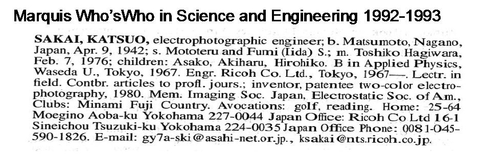
My carrier can be seen in many Marquis Who'sWho books.
The following is one of them.
gy7a-ski@asahi-net.or.jp
Back to the top of this page.