1.What is asymmetric electrostatic force ?
When direction of electric field reverses, intensity of electrostatic force that acts on point charge is not changed (Coulomb's law).
On the contrary, intensity of electrostatic force that acts on asymmetric shape charge conductor is decreased to half (Asymmetric electrostatic force)


Figure 2. Explanation figure of Coulomb's law and asymmetric electrostatic force.
"What is Coulomb's law ?"
When charge q is placed in electric field E, intensity of electrostatic force that acts on this charge can be calculated by the next equation.
F=qE
When polarity of charge is positive, the direction is the same as a direction of electric field. And when it is negative, the direction is reverse.
When direction of electric field is reversed, direction of electrostatic force is reversed too. But its intensity is not changed.
This phenomenon is called Coulomb's law.
Electrostatic problems have been analyzed by Coulomb's law for a long time. But, in fact Coulomb's law can not be applied to all problems.
Because, Coulomb's law is limited to special shape charge carriers. This limitation is written in all text book.
For example, the next question and answer is written in “Fundamentals of Physics”that is a very famous reference book for the freshman in the U.S.A.
Question:Is Coulomb's law correct with all charge carriers?
Answer:No, it is only correct with charged particle and hollow sphere.
I found over 100 internet homepages that explain Coulomb's law. Many of them describe "Coulomb's law is correct for point charge and hollow sphere that has uniform charge distribution on its surface"
"Suburbs of Coulomb's law"
Coulomb's law can not be applied to nonsphere shape. If so, how we can calculate the electrostatic force that acts on nonsphere shape charge carrier?
I can not find this answer not only in text books but also on internet. I thought this is very strange at first.
But, I changed my mind. I think now that this is natural. There are two reasons.
One reason is that target of electrostatic research has been powder for a long time. For example, xerographic toner and electrostatic coating's powder ink. They can be regarded as point charge.
The other reason is that in old days we calculated the electrostatic force mathematically without computer.
"A research of electrostatic force that acts on non-sphere shape conductor"
I have been researching a new electrostatic generator for a long time by myself. I used sphere shape charge carrier over five years. finally I understood that there is no solution by sphere shape.
Therefore, at first, I calculated the electrostatic force acting on box shape charge carrier by an simulation. Then I confirmed that result by an experiment.
The detail can be found in here."2009ESA annual meetig proceedings"
Next, I calculated the electrostatic force acting on 19 different shape charge carriers by a simulation. The details can be found here. "2010ESA annual meetig proceedings"
Then I confirmed that result by an experiment. The details can be found here."2011ESA annual meetig proceedings"
I will introduce some key points of them in the following.
"Simulation method that calculate the electrostatic force acting on non-sphere shape charge carrier."
At first, I selected some simple shapes that can be made from a few metal plates.
Because I made simulation program by myself, therefore, the program can not handle complex shape.
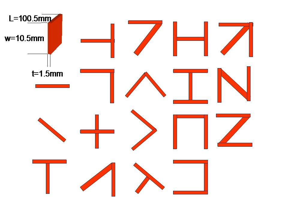
Figure 3 shows the shapes of the 19 different conductors. They were each made from one simple conductive plate.
The 19 differently shaped conductors that were placed between the two electrodes were each given a constant charge. The quantity of the charge was selected to be -0.1E-6[C]. The magnitude of the electric field between those electrodes was 1.0E+6 [V/m].
The electrostatic forces that act on 19 differently shaped charged conductors were simulated with the two-dimensional finite difference method. Figure 4 shows the result.
Figure 3 The front view of 19 different shape conductor.
"Simulation result"
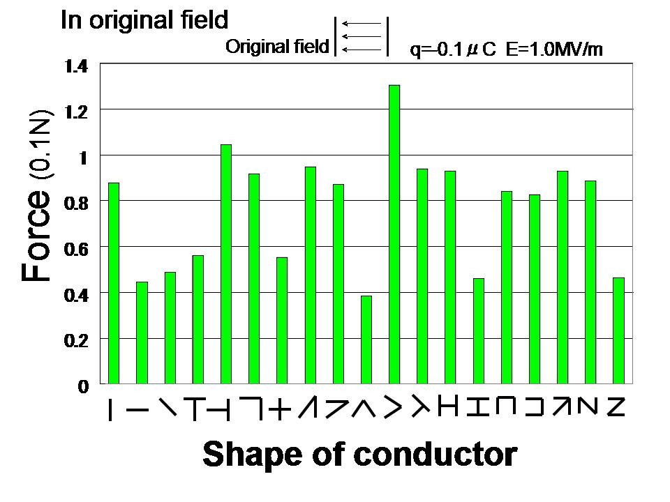
It is apparent from figure 4 that the magnitude of the electrostatic force that acts on different shape conductors are different depend on its shape, and a few non-spherical conductors have a larger electrostatic force than a spherical conductor in the same conditions, but many other non-spherical conductors have less force.
As mentioned before, the magnitude of the electrostatic force that acts on a spherical conductor that has -0.1E-6[C] in a parallel electric field of 1.0 E+6 [V/m] is 0.1 [N].
Figure 4 Electrostatic forces acting on 19 different charge carrier in original electric field.
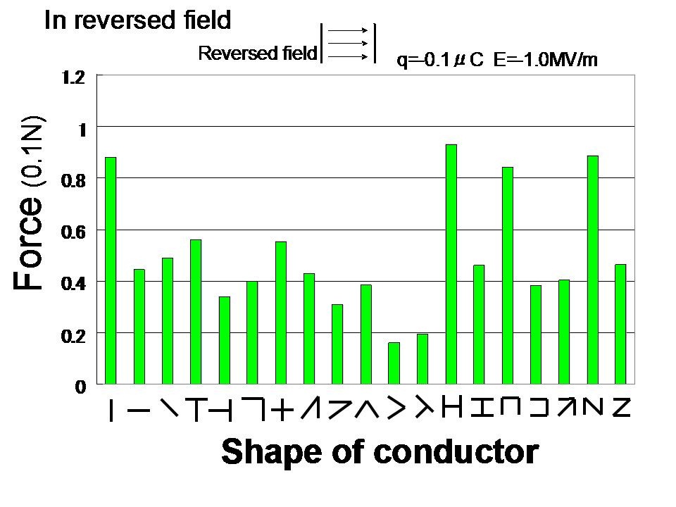
Next, the direction of the electric field was reversed. This field pattern will henceforth be called the reversed field.
Figure 5 shows the result. When the force in the reversed field, Frev. (figure 5), is compared with the force in the original field, Fori. (figure 4), it is apparent that the magnitude of the electrostatic force acting on some conductors changed.
To show this change clearly, the ratio of the two forces was calculated. Figure 6 shows the result.
Figure 5 Electrostatic forces acting on 19 different charge carrier in reversed electric field.
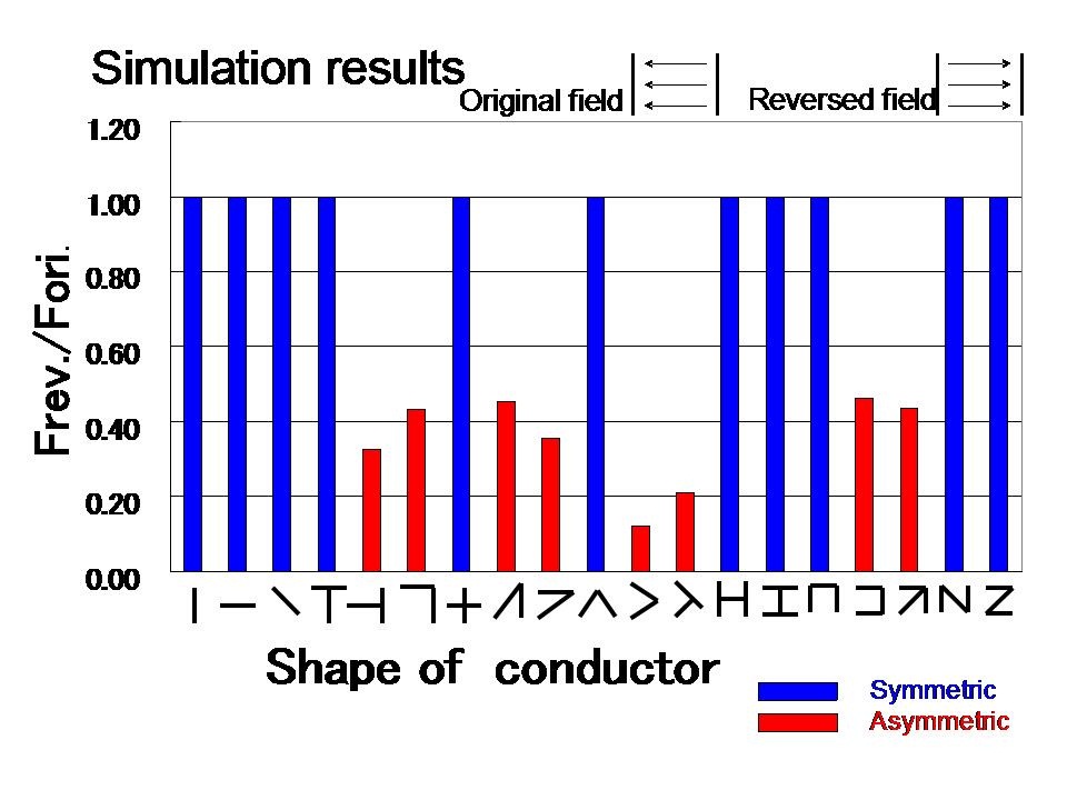
It is clear from figure 6 that when the direction of the electric field was reversed, the magnitude of the force acting on 11 of the conductors (blue bars) did not change. The shapes of those 11 conductors all have a common characteristic; namely, they are symmetric in the electric field direction.
On the contrary, the magnitude of the force acting on the other 8 conductors (red bars) changed strongly when the direction of the electric field was reversed. The shapes of those 8 conductors (red bars) are asymmetric in the electric field direction.
Therefore, the conclusion of this simulation is that if the shape of a conductor is asymmetric in the direction of the electric field, then the magnitude of the electrostatic force that acts on this conductor changes when the direction of the electric field is reversed.
This phenomenon was named the asymmetric electrostatic force by the author.
Next, this phenomenon must be confirmed by a real experiment.
Figure 6 The ratio of the force in the reversed field, Frev., to the force in the originalfield, Fori. Both forces act on 19 differently shaped conductors
"Confirming experiment of asymmetric electrostatic force"
The shapes and sizes of the 19 charge carriers (conductors) used for this experiment were almost the same as the shapes and sizes of the 19 conductors that were used in the simulation, with the exception of the thickness. The width, the height and the length of the 19 differently shaped conductor were about 10 mm, 10 mm and 50 mm, respectively.
The material used for the charge carriers (conductors) was aluminum, and the thickness was 0.2 mm. As the 19 conductors were made by hand, the size and shape were not perfect.
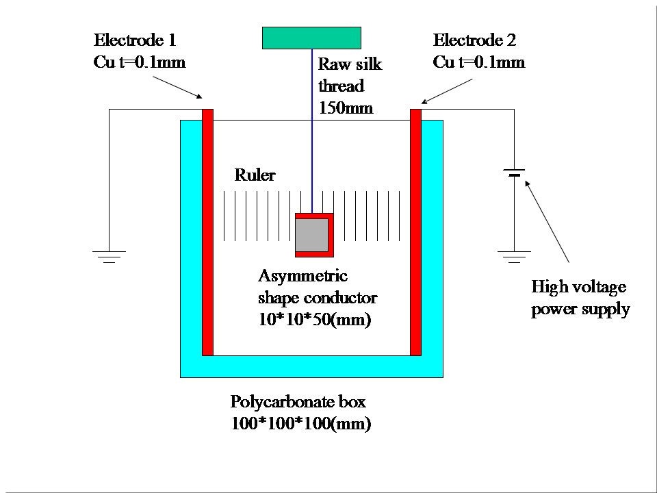
Figure 7 shows the front view of the experimental instrument.
The instrument consisted of two parallel electrodes and a ruler. The distance between the electrodes was 100 mm. One of them was connected to a high-voltage power supply, and the other was grounded. The differently shaped charge carriers (conductors) were hung one by one from insulating raw silk threads at the center of the two electrodes. The position of the conductor was measured by a ruler.
Figure 8 shows an explanatory drawing of the experimental procedure.
Figure 7 The front view of experimental instrument that measure electrostatic force
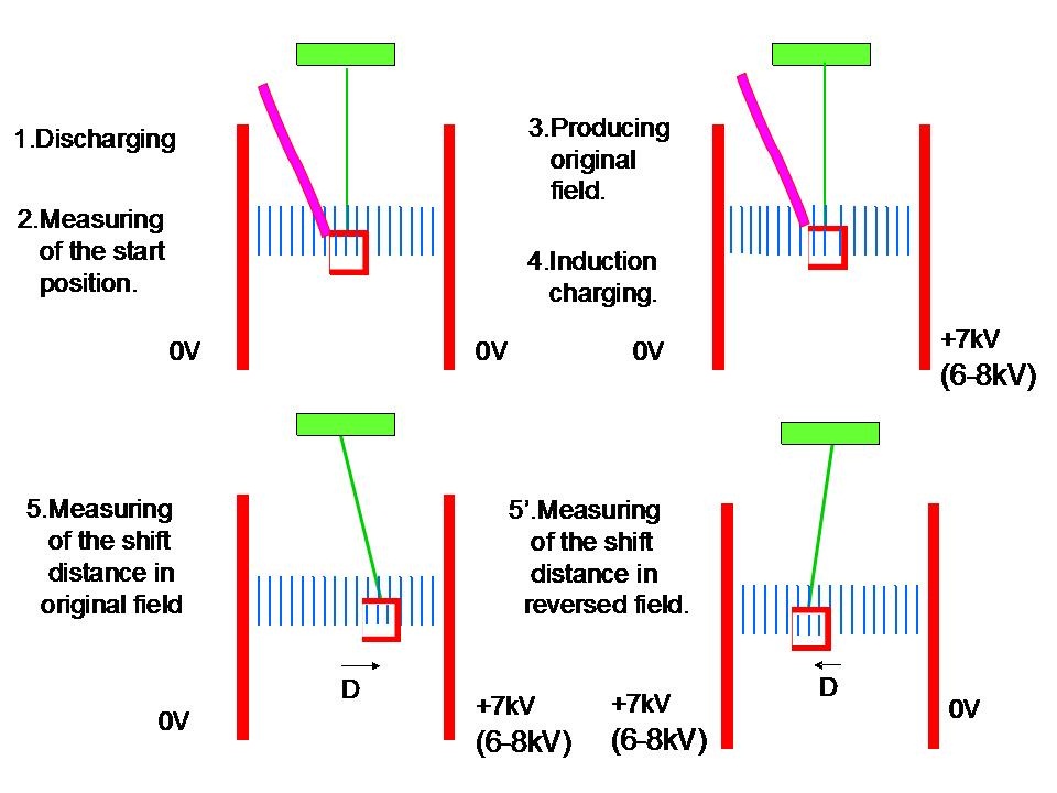
The experiment was performed using the following procedure:
1. The left and right electrodes were grounded, and the conductor was touched to the narrow grounded aluminum tape (Purple) for discharging.
2. The non-charged conductor was centered between the electrodes, and the position of the conductor was measured using the ruler. This position was the start position.(Figure 9 shows this situation by box shape conductor.)
3. The right electrode was charged to +7.0 kV, and the left electrode was grounded, creating the original electric field.
4. The conductor was touched to the narrow grounded aluminum tape (Purple) for induction charging. The tape was then kept away from the conductor so that a negative charge was maintained on the conductor.
5. Then, the conductor was shifted toward the right side by the electrostatic force acting on the conductor. The new position of the conductor was measured using the ruler. This position was the end position. (Figure 10 shows this situation) The difference between the start position and the end position was the shifted distance D of the conductor.
5'. Finally, the left electrode was charged to +7.0 kV and the right electrode was grounded, creating a reversed electric field, and the same experiment was performed again.(Figure 11 shows this situation) As a result, the shifted distance D in the reversed field is measured.
Figure 8 An explanatory drawing of the experimental procedure.

Figure 9: Start position in neutral field.

Figure 10: Shifted position in original field.

Figure 11: Shifted position in reversed field.
"Calculation of an electrostatic force from a experiment result"
The shifted distance D of the 19 conductors was measured 4 times, and the average value of the measured shifted distance D was used in the following calculation.
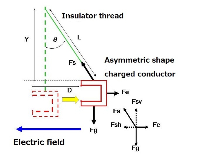
The shifted distance D is related to the length L and height Y of the thread, as shown in figure 12.
The ratio of lengths L:D:Y is the same as the ratio of the tensile strength of the thread Fs: the electrostatic force Fe: the gravity force Fg. The horizontal component of the tensile force Fsh is equal to the electrostatic force Fe, and the vertical component of the tensile force Fsv is equal to the gravity force Fg. Therefore, the electrostatic force Fe was calculated from the shifted distance D, the thread length L and the gravity force Fg, using the following formula:
 where L=150 mm and Fg=2.65 – 7.94 mN. Fg was calculated from the area of the conductor; the thickness of the Al plate and the specific gravity of Al.
Therefore, if the shifted distance D is measured, the electrostatic force can be calculated by the upper formula easily.
The electrostatic forces acting on the 19 differently shaped conductors in the original and reversed electric fields were calculated using this formula. Then the ratio of the force in the reversed electric field, Frev., to the force in the original electric field, Fori., was calculated. Figure 13 shows the result.
Figure 12. Calculation method of an electrostatic force from the shifted distance D
Confirmation of existence of asymmetric force by simulation and experiment
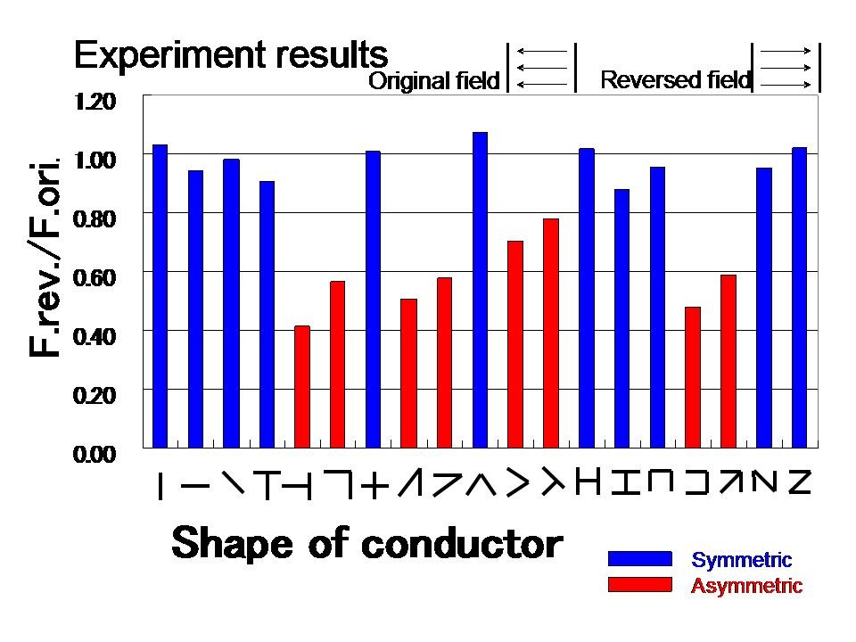
It is apparent from figure 13 that the force ratio of the 11 symmetrically shaped conductors (blue bars) is about 1.0. In contrast, the force ratio of the 8 asymmetrically shaped conductors (red bars) is less than 0.8. These experimental results are in general agreement with the simulation results (figure 6).
However, we can recognize a few difference between them. This result means that the simulation conditions were not sufficiently similar to the experimental conditions. Of course, achieving identical conditions between simulation and experiment is impossible. However, closer conditions between them should induce closer results between them.
Thus, the simulation conditions were reconsidered.
Figure 13 The ratio of the force in the reversed field, Frev., to the force in the originalfield, Fori. by experiment
In the simulation, it was assumed that the conductors would shift laterally while maintaining a constant incline. However, in the real experiment, each conductor’s incline changed when it shifted. Figure 14 shows three positions and their inclines.
It is apparent from figure 14 that, in the experiment, a conductor that shifted by 30 mm was inclined about 13 degrees. Therefore, re-simulation was performed with 13 degree incline.
Figure 14 Three positions of an asymmetric conductor, and their associated inclines.
Figure 15 shows the ratio of the force in the reversed field to the force in the original field that was calculated from the re-simulation.
This re-simulation result became closer to the experiment result (figure 13).
Figure 15 Re-simulation result with incline
The absolute differences between the simulated force ratios and the experimental force ratios were calculated to show their relationships clearly. Figure 16 shows the result.
If the experimental results agreed with the simulation results perfectly, then the difference between the force ratio of the simulation and the force ratio of the experiment would be zero.
Unfortunately, however, this was not a precise experiment; the 19 conductors were handmade, and the position of each conductor was measured by human eyes.
Therefore, a difference of 0.2 is within the expected error.
This means that the experimental results agree almost entirely with the re-simulation results.
Therefore, the existence of the asymmetric electrostatic force has now been nearly confirmed.
Figure 16 Absolute value of the difference between the ratio of re-simulation and the ratio of the experiment.
"A reasonable cause of the asymmetric force."
The next simulation was done to establish the theory of the asymmetric electrostatic force. The electrostatic force acting on conductors of different shapes was simulated. The different shapes are a cup and a cylinder and a disc. The disc was made of the bottom face of a cup, and the cylinder was made with the remainder, as shown in Figure 17.
The three different conductors were given the same charge of -2.0 nC, and the intensity of the electric field was changed from +0.3 MV/m to -0.3 MV/m. The simulation results are shown in Figure 18.
Figure 17 A cup shape conductor and its two parts (a cylinder and a disk)
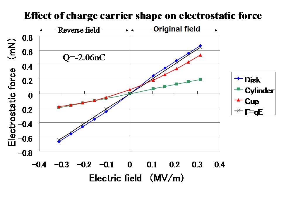
It is clear from figure 18 that the electrostatic force on the cup is almost same as the electrostatic force on the disc in the original field, but the electrostatic force of the cup is same as the electrostatic force of the cylinder in the reversed field.
This result suggests that the charge distribution of the cup is almost similar to the charge distribution of the disc in the original field, and the charge distribution of the cup is similar to the charge distribution of the cylinder in the reverse field.
Therefore,the charge distribution of the five surfaces of the cup was calculated from the simulation result.
The results are shown in Figures 19.
Figure 18 Electrostatic forces that acts on a cup and its two parts (a cylinder and a disk)
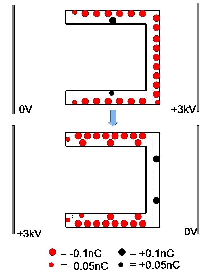
Figure 19 shows the calculated charge distribution in the cup from the simulation result.
In the original electric field, many electrons (red spheres) gather at the front (right) surface of the vertical disk of the cup. As a result, a strong electrostatic force acts on the front (right) surface of the cup. The direction of the force is perpendicular to the front surface.
In contrast, when the direction of the electric field is reversed, the electrons (red spheres) move toward the edge (left) surface of the cylinder part. However, the edge is too narrow for all the electrons to gather. As a result, many electrons are stopped at the peripheral area of the cylinder part.
They do not contribute to produce electrostatic force that carries the cup. This is because the direction of the electrostatic force that acts on those electrons is perpendicular to the peripheral surface of the cup, and they cancel each other out at an interval of 180 degrees.
Therefore, the reason of the asymmetric electrostatic force is summarized in two points as follows:
1.Charge distribution in asymmetric shape conductor changes asymmetrically when the direction of the electric field is reversed.
2.Electrostatic force that acts on the electrons (charges) on the parallel part to the electric field can not contribute to produce effective force
This proposed theory of the asymmetric electrostatic force must be quantitatively confirmed by a real experiment.
If you can not understand clearly, please see this comic.Across a frozen lake by assisting of strong wind,
Figure 19 Chrge distribution in the cup in original and reversed electric field.
"Go forward in reversal electric field, like a yacht in a head wind"
Change of force depending on its shape is not rare phenomenon.
For example, a force that acts on a object in fluid is different depending on its shape. If the shape is sphere, the force can be easily calculated by Stokes's law.
However,when it is non-sphere shape, the force can not be calculated. Therefore, a model plane, a model car and a model ship are placed in fluid room, and the real force have been measured.
Especially, a yacht is very interesting. Wind force that acts on the sails of the yacht becomes strong in follow wind,but weak in head wind.
Furthermore, a yacht can go ahead obliquely in head wind, Then, I wondered why a charge carrier can not go ahead in a reversed electric field. Accordingly, I thought many shapes of a charge carrier, and I calculated the force that acts on them by a simulation.
At finaly, I found the special shape for this target. If you have interest it, please see the fifth chapter of the next book.
Asymmetric Electrostatic Forces and a New Electrostatic Generator
Or, please see the fifth section of the first chapter of the next book.
Electrostatics: Theory and Applications
"There are 3 kinds asymmetric electrostatic forces."
It is well known that ordinary electrostatic force consist of Coulomb's force, gradient force and image force.
Also, the asymmetric electrostatic force consist of 3 kinds force. The asymmetric electrostatic force like Coulomb's force has been explained here. The other two asymmetric electrostatic forces has been explained in the upper books.
Finally, I introduce all my papers of asymmetric electrostatic force.
"List of Sakai's papers of asymmetric electrostatic force."
1. ESA (The Electrostatics Society of America) Proceedings.
- 2006 P.137 "Electrostatic power generating method with using image force"
- 2007 p.155 "A symmetric conductor in convergent field vs, an asymmetric conductor in parallel field"
- 2008 D3 "An experiment result which confirms the fourth electrostatic firce"
- 2009 P2.08 "The electrostatic force that acts on the charged conductor in a high electric field" "2009ESA annual meetig proceedings"
- 2010 G4 "Electrostatic force that acts on non-sphere shape charged conductors" "2010ESA annual meetig proceedings"
- 2011 B4 "A simple experiment result that confirmed asymmetric electrostatic force" "2011ESA annual meetig proceedings"
2. Journal of Electrostatics
- Volume 67 (2009) issue 1 P.67 "An overlooked electrostatic force that acts on a non-charged asymmetric conductor in a symmetric (parallel) electric field"
- In submitting "Asymmetric electrostatic force"
3. Books by published by Nova Science Publisher.Ins New york
- "Asymmetric Electrostatic Forces and a New Electrostatic Generator"
Asymmetric Electrostatic Forces and a New Electrostatic Generator
- "Electrostatics; Theory and Applications" (collaboration)
Electrostatics: Theory and Applications
Back to the top of this page.
Back to the top page.