 |
Reciprocating Engine Analysisby EXCEL |
It was the highest priority to find out what is the power output of the reciprocating engine using gas generated from Wood Gasification Reactor. For this purpose, thermodinamic calculation was conducted for the gasoline engine installed on the Wood Buggy. Then power output for the gas fuel case was calculated applying the same (Actual Thermal Efficiency)/(Theoretical Efficiency) of the gasoline fuel case.
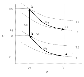
Internal combustion engine is an open cycle as shown in the following PV diagram.

PV diagram
Ideal Gas was assumed. Cp were calculator from the same equations and parameter used in Gasification Reactor design. Arithmetic average temperature was used for Cp calculation. Direct Goal Seek method was used for convergence of the outlet temperature.
P (atm)
V (m3/kgmol)
n (kgmol/h)
R = 0.0887 (kcal/Nm3 deg.K)
T (deg K)
Cp - Cv = R
r = Cp / Cv = Cp / (Cp - R)
m = r (polytropic efficiency) (m > 1)
Compression process (A to B) is described as follows. Gasoline was assumed to stay as liquid during compression process. Therefore, n1 is only intake air. In the gas fuel case, n1 is gas and air mixture. Joule-Thomson Effect at throttle valve was assumed zero because the gas was assumed as ideal gas. Polytropic efficiency of 100% was taken for calculating theoretical efficiency.
P1V1m = P2V2m
T2/T1 = (P2/P1)(m - 1)/m
W1= 24.2179 n1(P2V2 - P1V1) / (m - 1)
Combustion process (B to C) is described as follows. It was assumed that all gasoline evaporate in this stage. DEphase is the enthalpy change of this vaporization. DH is the heating value. n2 is moral flow of exhaust gas.
DH - DEphase = 24.2179 n2 Cp (T3 - T2)
T2 / P2 = T3 /P3
Expansion process(C to D) is described as follows. Polytropic efficiency of 90% was taken.
P3V2m = P4V1m
T4/T3 = (P4/P3)(m - 1)/m
W2 = 24.2179 n2 (P3V2 - P4V1) / (m - 1)
All in all,
Theoretical Thermal Efficiency = (W2 - W1)/ DH
(Actual Efficiency) / (Theoretical Efficiency)
It was assumed that (Actual Efficiency) / (Theoretical Efficiency) is specific for each machine and constant for different operational mode. It was also assumed that engine is driving electric generator and running at constant speed.
Calculation results for power generation purpose are shown below.
This program also can simulate Miller cycle engine by taking P2/P1=10 and P3/P4=13.
May 6, 2003
Rev. January 24, 2010