
|
|
Design Program forPower Generation by Biomass GasificationVersion 3Greenwood |
Introduction
As introduced in Biomass Gasification Project, it was Mr. Greenwood's responsibility to make basic design calculations to determine operating condition and equipment specifications. For this purpose, he had to make chemical equilibrium calculation, stoichiometric calculation, enthalpy calculation and engineering calculation. He has developed a computer program of 676kb, 28sheets size using MS Excel. Using this program, he designed and made studies for:
(1) Wood Gas Cart
(2) Comparison of Wood v.s. Charcoal
During times of the World War II, biomass gasification technology was developed to fill shortage of petroleum.
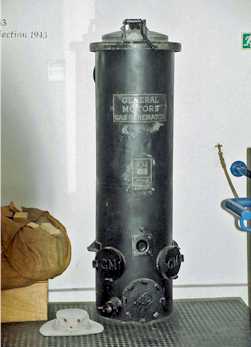
Gasifier used in Denmark in war time (photo by Mr. Cooper)
According to a design manual published by Forestry Department of FAO (Food Agricultural Organization) of UN. there are four types of reactor design.
(1) Up-draught or counter current gasifier
(2) Cross-draught gasifier
(3) Downdraught or co-current gasifier
(4) Fluidized bed gasifier
Downdraught or co-current gasifier is most suited for supplying gas to reciprocating engine. There are 3 different types among Downdraught or co-current gasifier.
Following table shows appropriate "Hearth Load" for each type.
Wood based Hearth Load |
Gas based Hearth Load |
|
kg/cm2/h |
Nm3/cm2/h |
|
| No Throat | 0.03 |
0.07 |
| Single Throat | 0.11 |
0.25 |
| Double Throat | 0.4 |
0.9 |
Further recommendations by the manual by FAO are:
-nozzle air inlet velocities should be around 30-35m/sec
-throat inclination should be around 45-60o
-height of the lower hearth (expanding zone) below throat (narrowest constriction) should be more than 20cm.
-height of the air inlet nozzle plane above throat should be 10cm above narrowest constriction of the height determined by following equation.
(nozzle height)/(throat dia.)=19.6*(throat dia.)-0.64
-hearth diameter at air inlet height should be 10cm larger than throat diameter in case of single throat and about 20 cm larger than the throat diameter of the throat dia. in case of double throat design.
1. Input Data (Input Sheet)
<Biomass Composition>
Carbon/hydrogen/oxygen element ratio (CHO elemental ratio) of the dry biomass was calculated from cellulose(C6H10O5)n and lignin (C18H24O11)n. It was assumed that 70% is cellulose and remaining 30% is lignin. The average formula becomes(C6H9.4O4.6)n. Biomass composition is calculated from CHO elemental ratio. Chemical formula for biomass were taken from Reference 1. Water and ash content were assumed 30 wt% and 3 wt% respectively.
|
MW |
kg/h |
wt % |
kgmol/h |
mol. % |
elements |
|
|
C in Biomass |
12 |
3.018 |
31.1 |
0.251 |
25.15 |
6 |
|
H in Biomass |
1 |
0.394 |
4.1 |
0.394 |
39.40 |
9.4 |
|
O in Biomass |
16 |
3.085 |
31.8 |
0.193 |
19.28 |
4.6 |
|
Water |
18 |
2.911 |
30.011 |
0.162 |
16.17 |
|
|
Ashes |
- |
0.291 |
3 |
|||
|
Total |
9.698 |
100.0 |
1.000 |
100.00 |
20 |
|
|
MW |
9.698 |
|||||
|
Items |
Unit |
Figures |
||||
|
Specific Gravity of Biomass |
- |
0.5 |
||||
|
Void Space of Biomass Container |
% |
40 |
||||
Input Biomass Data
Blue figures are input data, yellow figures are calculated from (C6H9.4O4.6)n
<Process Flow Scheme>
The basic process flow scheme was established as follow.
Process Flow Scheme
Biomass is charged batch wise into the container. Ashes and condensate will also be discharged batch wise.
When water content of biomass is more than 30wt% and when size of reactor is small scale, heat recovery to feed biomass and/or to air is needed. Slim reactor is recommended to achieve good heat recovery. Heat balance is adjusted by insulation thickness and un-insulated surface.
Air nozzles are split into n numbers.
Gas cooler shall be big enough to cool down gas near ambient temperature and condensate shall be removed. The size of the cooler will be determined for start up operation which generate much of the water. Condensate accumulation capacity will be provided in condensate separator for accumulating all water generated during start up operation. If engine is started before water level becomes low, engine oil might be fouled by condensate.
<Engine Generator Specifications>
Design of reactor will be made to meet commercially available gasoline fueled engine generator specifications.
|
Cylinder Volume |
cc |
50 |
|
Number of Cylinder |
- |
1 |
|
Compression Ratio |
- |
6 |
|
Cycle |
- |
4 |
|
Rotation |
rpm |
6,000 |
|
Excess Air Ratio |
- |
1.1 |
|
Shaft Power |
PS |
1.79 |
| Generator Efficiency |
% |
95 |
Engine Generator Specification
When you input certain biomass feed rate, the program answer back needed cylinder volumes. You can then adjust feed rate to meet available engine size.
<Reactor Specifications>
After once though simulation you can adjust equipment size.
As FAO manual shows two different figures of Hearth Load, intermediate figures of both was taken as the basis of throat diameter.
|
Items |
Unit |
Figures |
|
Biomass Consumption for Gasification |
kg/h |
1.7 |
|
Biomass Consumption for Start Up |
kg/h |
0.8 |
|
Biomass Container Diameter: d1 |
cm |
20 |
|
Hearth Throat Diameter: d2 |
cm |
4.6 |
|
Hearth Bottom Diameter: d3 |
cm |
15 |
|
Reactor Diameter: d4 |
cm |
30 |
|
Insulation Cover Diameter: d5 |
cm |
36 |
|
Start up Air Intake Manifold Diameter: d6 |
cm |
2.5 |
|
Recommended Gas Based Hearth Load |
Nm3/cm2/h |
0.25 |
|
Recommended Biomass Based Hearth Load |
kg/cm2/h |
0.11 |
|
Number of Start up Air Nozzles: n |
- |
3 |
|
Start up Air Nozzle Pipe Diameter: d7 x n |
cm |
1.9 |
|
Start up Air Nozzle Diameter: d8 x n |
mm |
6 |
|
Water Cooler Inner Pipe Diameter: d9 |
cm |
2.5 |
|
Cooler Water Outer Pipe Diameter: d10 |
cm |
5 |
|
Condensate Accumulator Diameter: d11 |
cm |
30 |
|
Engine Air Intake Pipe Diameter: d12 |
cm |
1.9 |
|
Engine Air-Gas Mixture Pipe Dia.: d13 |
cm |
2.5 |
|
Height of Biomass Container : h1 |
cm |
110 |
|
Height of Upper Hearth (throttling zone): h2 |
cm |
15 |
|
Height of Lower Hearth (expanding zone): h3 |
cm |
20 |
|
Height of Grating from bottom of Hearth: h4 |
cm |
10 |
|
Height of Ash Accumulation: h5 |
cm |
20 |
|
Height of Air Nozzle from Hearth Throat: h6 |
cm |
10 |
|
Height of Uninsulated Reactor: h7 |
cm |
100 |
|
Height of Baiomass Container Neck: h8 |
cm |
20 |
|
Height of Reactor Insulation |
cm |
55 |
|
Heat Recovery Length of Nozzle Pipe |
cm |
90 |
|
Heat Recovery Length of Container |
cm |
90 |
|
Insulation Thermal Conductivity k (Rock Wool) |
kcal/C/m/h |
0.037 |
|
Insulation Thickness d |
mm |
3 |
|
Film Coefficient of Annular Space Gas hi |
kcal/m2 h C |
10 |
|
Film Coefficient of Natural Convection of Air ho |
kcal/m2 h C |
10 |
|
Water Cooler Cooler Pipe Length: L |
m |
6 |
|
Ambient Temperature |
deg. C |
25 |
|
Water Temperature |
deg. C |
25 |
|
Water Outlet Temperature at Design Condition |
deg. C |
50 |
|
Diameter of Ash Particulate |
microns |
160 |
Input Equipment Data
<Operational Procedure>
Operation start by putting ignited charcoal into the hearth. Start up induced fan keeps necessary air flows during biomass charge into biomass container. Start up air nozzle keeps necessary flow velocity to burning spot. After hatch of biomass charge mouth is closed, Start up air is throttled. Adequate burnable gas quality is checked by igniting gas coming from induced fan. After engine is started, start up induced fan is stopped and start up air valve could be throttled.
2. Chemical Equilibrium (Free Energy Sheet)
There are two ways of calculating chemical equilibrium. One way is a method via chemical equilibrium constants Kp as described in Appendix. And second is minimizing Gibbs free energy of the entire system. In any case, every thing starts from calculating free energy of formation.
Biomass is a complex material described generally as(CaHbOc)n+H2Om and it is difficult to establish chemical reaction equation. Therefore, only viable method is minimizing free energy.
In this model, I have assumed that free energy of formation of biomass is a molar average of the constituting element. This means that heat of formation of dry biomass DH0fdry is zero. But when you have a data of actual heat of combustion of the biomass, then you can calculate.
DH0fdry=(heat of combustion calculated from elements) - (measured heat of combustion of the biomass)
As
Heat of combustion calculated from elements=0
Then
DH0fdry= - measured heat of combustion of the biomass
You can use this for Gibbs Free Energy calculation and for heat balance. Here I assumed
DH0fdry=0
Generally, standard free energy of formation at T is defined by Gibbs-Helmholtz as
T
DG0f t= -
T∫DH0f/T2
dt
25
Integrating it, you can obtain
DG0ft = DH0f -DHt -TDS0 (kcal/kgmol)
The value of DH0f is published in Thermodynamics by Kojima 1969
DH0f (kcal/kgmol) |
|
C |
0 |
| O2 |
0 |
N2 |
0 |
CO2 |
-94,060 |
CO |
-26,415 |
H2 |
0 |
H2O |
-57,798 |
CH4 |
-18,889 |
3. Enthalpy Calculation (Enthalpy Sheet)
Enthalpy of the gas could be calculated from specific heat at constant pressure Cp. Cp is a function of temperature T. Enthalpy could be calculated from an equation, having a integral form of Cp as follows.
T
DHt = ∫CpdT
25
Integral form of above equation for each substance are tabulated in the following table. Where H* is an integral constant.
|
Components |
Specific Heat Cp |
Enthalpy DHt |
a | b | c |
|
- |
kcal/kgmol deg.K |
kcal/kgmol |
- | - | - |
| C | a + bT + c/T2 | H* + aT + (b/2)T2 - c/T | 2.673 | 0.002517 | -116,900 |
| O2 | a + bT + c/T2 | H* + aT + (b/2)T2 - c/T | 8.27 | 0.000258 | -187,700 |
| N2 | a + bT | H* + aT + (b/2)T2 | 6.5 | 0.001 |
- |
| CO2 | a + bT + c/T2 | H* + aT + (b/2)T2 - c/T | 10.34 | 0.00274 | -195,500 |
| CO | a + bT | H* + aT + (b/2)T2 | 6.6 | 0.0012 | - |
| H2 | a + bT | H* + aT + (b/2)T2 | 6.62 | 0.00081 | - |
| H2O | a + bT + cT2 | H* + aT + (b/2)T2 + (c/3)T3 | 8.22 | 0.00015 | 0.00000134 |
| CH4 | a + bT | H* + aT + (b/2)T2 | 5.34 | 0.0115 |
- |
Individual enthalpy sheet were prepared for reaction temperature, reactor inlet and outlet temperature, cooler outlet etc.
4. Entropy Calculation (TS Sheet)
TDS0 could be calculated by integration Gibbs-Helmholtz equations.
|
Components |
Specific Heat Cp |
TDS0 |
a | b | c |
|
- |
kcal/kgmol deg.K |
kcal/kgmol |
- | - | - |
| C | a + bT + c/T2 | TS* + aTlnT + (b/2)T2- c/T | 2.673 | 0.002517 | -116,900 |
| O2 | a + bT + c/T2 | TS* + aTlnT + (b/2)T2 - c/T | 8.27 | 0.000258 | -187,700 |
| N2 | a + bT | TS* + aTlnT + (b/2)T2 | 6.5 | 0.001 |
- |
| CO2 | a + bT + c/T2 | TS* + aTlnT + (b/2)T2 - c/T | 10.34 | 0.00274 | -195,500 |
| CO | a + bT | TS* + aTlnT + (b/2)T2 | 6.6 | 0.0012 | - |
| H2 | a + bT | TS* + aTlnT + (b/2)T2 | 6.62 | 0.00081 | - |
| H2O | a + bT + cT2 | TS* + aTlnT + (b/2)T2 + (c/6)T3 | 8.22 | 0.00015 | 0.00000134 |
| CH4 | a + bT | TS* + aTlnT + (b/2)T2 | 5.34 | 0.0115 |
- |
TS* is integral constants.
5. Standard free energy of formation at T (Free Energy Sheet)
By following equation
DG0ft =DH0f -DHt -TDS0 (kcal/kgmol)
We get following diagram.
Standard Free Energy of Formation
6. Gas Composition (Gibbs Sheet)
Chemical equilibrium achieves minimum Gibbs free energy. Gibbs reactor module of process simulator PRO/II use this method. Standard Gibbs free energy DGif0 of formation of each substance i is described by following equation.
DG0fi = DH0fi - T DS0fi
Free energy change of the reaction is
DG0=(SXiDG0fi)prod - (SXiDG0fi)feed
Here,
Objective Function=DG0
Using Solver of EXCEL you can find Xi of product gas which will give minimum value of above equation with the constraint of Xi>0
XC、XO2、XH2、XN2 in product gas could be directly calculated by following material balanace.
Regarding carbon element,
(XC+XCO2+XCO+XCH4)prod=(Cdry)feed
When unburned carbon XC was found, increase air injection rate XO2 and consume all biomass.
Regarding oxygen element,
(2XO2 + 2XCO2 + XCO + XH2O)prod=(Odry+XH2O+2XO2)feed
Regarding hydrogen element,
(2XH2 + 2XH2O + 4XCH4)prod=(Hdry+2XH2O)feed
Regarding nitrogen element,
(XN2)prod=(XN2)feed
Thus unknown variables of the objective function becomes 4 i.e. XCO2、XCO、XH2O、XCH4.
Initial estimate of the Xi is important. I have used a set of values calculated by PRO/II on the same condition.
When wet biomass feed rate is CHO+Water=1.7kg/h and air feed rate is 1.923kg/h, the composition of the generated gas in mol. % at each reaction temperature are shown in the following chart. Some unburned carbon is generated at the temperature from 500 to 600oC.
Gas Composition
Flue gas composition during start up operation was calculated from stoichiometric calculation, assuming that only CO2 and H2O are generated.
7. Heat Balance Calculation (Balance Sheet)
Based on calculated mol. flow of gas and enthalpy of each component, total gas enthalpy was calculated.
<Gassificaton Operation>
Heat balance of the gasification operation is described like;
DHout = -DH0 + DHt - DHloss+ DHin
DHout is an enthalpy of product gas leaving the reactor at temperature of Tout. From those, you can calculate gas temperature leaving the reactor Tout by Goal Seek method of EXCEL.
Tout
DHout = ∫SXiCpi dT
25
DH0 is standard heat of reaction. Value having minus figures are exothermic reactions. plus figures are endothermic reactions.
DHt is an enthalpy of gas at reaction temp. T
DHloss is a heat loss from the wall of reactor and could be calculated by engineering calculation.
DHin is incoming enthalpy of biomass. As air flow is normally zero for wood. Some air might be needed for char coal but heat is recycled internally. Air for startup operation also recycles heat internally. Therefore it has no influence on overall heat balance. Biomass is charged batch wise near standard condition and heated up to stabilizing temperature during start up operation. Therefore,
DHin= DHbiomass
Here, DHbiomass is an enthalpy of feed biomass
DHbiomass = DHdry + DHwater
DHwater = Xmoisture in biomass(-10,514kcal/kgmol)
DHdry is an enthalpy of dry biomass, DHwater is an evaporation of moisture contained in the biomass. Latent heat = -10,514 kacal/kgmol).
<Startup Operation>
During startup, DHin= 0 and container heating up to stable temperature would behave like heat loss. Therefore,
DHout = -DH0 + DHt - DHloss+ DHin - DHbiomass
Heat balance shall be within the equipment size of gasification operation. Burning temperature shall be 900oC which is maximum allowable temperature for thermal resistance metal.
<Cooler>
Heat balance around gas cooler is
DHduty = DHout - DHcool
Outlet enthalpy of gas cooler DHcool is
Tcool
DHcool = ∫SXiCpi dT
25
Find Tcool by goal seek。
Heat balance calculation was conducted for temperature of 400oC、600oC、700oC、800oC、900oC and for start up operation. Engine calculation was conducted for 400oC、600oC、700oC (Design Case).
<Others>
Combustion heat (LHV) of biomass dry basis and wet basis and gas were calculated from standard heat of formation. Estimated figures well meet the published heating value of biomass. This means that assumption made at the beginning is almost true. The assumption made was that free energy of formation of biomass is a molar average of the constituting element.
Pressure profile is adjustable reflecting pressure drop calculation conducted in engineering calculation by direct replacement.
Volumetric flow and gas density of various position were calculated here.
Results of Heat Balance
Heat of reaction in above graph means standard heat of reaction -DH0 at 25oC
8. Engineering Calculation (Engineering Sheet)
Using all information made available, following items were calculated.
(1) Stoichiometric air to fuel ratio (air/gas) ; Stoichiometric calculation of gas combustion.
(2) Lower Flammability Limit of the Gas ; Data source is Reference 4.
(3) Upper Flammability Limit of the Gas ; Data source is Reference 4.
(4) Water Dew Point of the Gas ; Data source is Reference 4.
(5)Energy Conversion Efficiency of the Gasifier (Ratio of total energy contained in the gas and that contained in the biomass.
(6) Upward gas velocity in the annular space shall be lower than the terminal velocity of 160 micron ash particulate calculated by Stokes' Law taken from Reference 6.
(7) A container is required to house enough feed biomass. Input value of Sp. Gr. of biomass and average void e were used for calculation of batch wise operation duration.
(8) Diameter of the throat was selected to ensure uniform contact of gas and charcoal based on FAO manual.
(9) Pressure drop of the air nozzle was calculated from orifice calculation equation of Reference (9)
(10) Pressure drop of the throat was calculated by Carman's equation of Reference (9)
(11) Pressure drop of the gas cooler was calculated by Hagen-Poiseuille equation of Reference (9)
(12) Pressure drop of the engine choke to match with total system pressure profile was calculated by orifice calculation of Reference (9)
(13) Head requirements of startup induction fan could be determined similarly.
(14) Gasificaion air preheating was calculated from assumed heat transfer coefficient of 10kcal/m2 h C.
(15) Biomass preheating would be completed during start up operation. Once certain temperature is achieved no further heating would occur. Heat transfer would be through container wall. Input heat transfer coefficient of natural convection was used. This is sufficient to vaporize all water content in biomass.
(16) Heat loss of the reactor is calculated for insulated portion and bare portion separately. Insulated portion considers insulation thickness, thermal conductivity of rock wool and film coefficient of natural convection. Bare portion does not consider insulation.
(17) Overall heat transfer coefficient of gas cooler was calculated from gas side and water side film coefficient. Goal Seek of water rate is possible for better water side film coefficient estimation.
(18) Cooling water flow rate is determined by duty and outlet temperature specified by input sheet.
(19) Maximum condensate height is estimated.
9. Docking with Engine Analysis Program (Engine Sheet)
Normally, commercially available gasoline engine is converted to gas fuel. Reciprocating Engine Analysis Program will calculate intake gas volume and thermal efficiency form gasoline engine performance data. In this case, theoretical thermal efficiency is calculated assuming polytropic efficiency is 100%. Then acutual/theoretical ratio is calculated. It was assumed that the same ratio could be applied to gas.
Gas composition at 700oC was selected as design feed gas composition. Combustion Sheet will calculate gas combustion stoichiometry and generate flue gas composition.
Cp Sheet calculate Cp for air gas mixture compression and Cp for exhaust gas expansion.
Finally, Engine Sheet make whole reciprocating engine cycle calculation. Goal Seek calculation is needed for convergence of various temperature.
In the case of power generation, normally speed is kept constant and throttle valve reduce suction pressure low.
10. Calculation Procedure
The calculation procedures are illustrated in the following chart.
Calculation Flow Chart
Solver of Gibbs Sheet only need to use once when biomass composition is changed.
Balance Sheet has 19 Goal Seek calculations. Macro program was developed to do many Solver calculations automatically. Goal Seek for pressure profile is not needed as it does not affect entire systems.
Goal Seek for water forced flow film coefficient has small impact on cooler design.
Please read "User Manual for Design Program for Power Generation by Biomass Gasification Version 3"
11. Calculation Results (Output Sheet)
Following table show the summary of the design calculation.
|
Items |
Unit |
Startup |
700C(Design) |
|
Engine Load |
% |
- |
100 |
|
Biomass Load |
% |
47.1 |
100 |
|
Biomass Consumption |
kg/h |
0.80 |
1.70 |
|
Batch Volume |
kg |
9.3 |
9.3 |
|
Batch Duration |
h |
5.5 |
11.7 |
|
Air Rate @ Intake Manifold |
m3/h |
2.24 |
1.63 |
|
Engine Air Intake Rate (with excess air) |
vol/vol |
- |
3.88 |
|
Engine Air and Gas Mixture Intake |
Nm3/h |
- |
7.8 |
|
Engine Intake Pressure |
atm |
- |
0.89 |
|
Gas Heating Value (LHV) |
kcal/Nm3 |
- |
965 |
|
Flammable Gas Contents |
% |
- |
19.3 |
|
Lower Flammability Limit |
% |
- |
7.1 |
|
Upper Flammability Limit |
% |
- |
74.2 |
|
Total Gas Energy (Eff.=100%) |
kW |
- |
4.4 |
|
Biomass Heating Value (LHV) |
kcal/kg |
4,733 |
4,733 |
| Biomass Heating Value (LHV) |
kcal/dry kg |
7,065 | 7,065 |
|
Conversion Efficiency (Gas Energy/Biomass Energy) |
% |
- |
46.9 |
|
Engine Speed |
rpm |
- |
6,000 |
|
Engine Efficiency |
% |
- |
12.9 |
|
Engine Output |
PS |
- |
0.77 |
|
Engine Output |
kW |
- |
0.56 |
|
Generator Efficiency |
% |
- |
95 |
|
Power Output |
kW |
- |
0.54 |
|
AC Output |
W |
- |
439 |
|
DC Output |
W |
- |
96 |
|
Reaction Temperature |
deg. C |
900 |
700 |
|
Start up Air Preheating Temperature |
deg. C |
694 |
- |
|
Biomass Preheating Temperature |
deg. C |
445 |
337 |
|
Reactor Outlet Gas Temperature |
deg. C |
447 |
383 |
|
Cooler Outlet Gas Temperature |
deg. C |
32.6 |
31.2 |
|
Heat Loss |
kcal/h |
4,008 |
3,308 |
|
Hearth Load (Biomass base): Recommended by FAO<0.11 kg/cm2/h |
kg/cm2/h |
0.048 |
0.102 |
|
Hearth Load (Gas base): Recommended by FAO<0.25 Nm3/cm2/h |
Nm3/cm2/h |
0.190 |
0.235 |
|
Choke Velocity |
m/sec |
- |
13.2 |
|
Air Nozzle Velocity: Recommended by FAO>30-35m/sec |
m/sec |
24.8 |
18.1 |
|
Throat Velocity (Superficial Base) |
m/sec |
2.7 |
2.4 |
|
Average Annular Space Velocity |
m/sec |
0.113 |
0.102 |
|
Ashes Terminal Velocity |
m/sec |
- |
0.190 |
|
Air Average Velocity in Nozzle Pipe |
m/sec |
2.5 |
1.8 |
|
Reactor Outlet Gas Velocity |
m/sec |
9.04 |
8.13 |
|
Cooler Outlet Gas Velocity |
m/sec |
2.4 |
2.5 |
|
Engine Air Intake Pipe Velocity |
m/sec |
- |
3.80 |
|
Engine Air-Gas Mixture Velocity |
m/sec |
- |
4.95 |
|
Reactor Operation Pressure |
atm |
0.780 |
0.889 |
|
Engine Suction Pressure |
atm |
- |
0.891 |
|
System Pressure Drop (Nozzle, Throat, Cooler) |
kg/cm2 |
0.228 |
0.112 |
|
Choke Orifice Pressure Diameter |
mm |
- |
10.2 |
|
Water Flow Rate |
kg/h |
17 |
17 |
|
Water Velocity in Cooler |
m/sec |
0.001 |
0.002 |
|
Cumulative Hot Water |
kg |
201 |
96 |
|
Velocity in Condensate Accumulator |
m/sec |
0.016 |
0.018 |
|
Water Dew Point |
deg. C |
<0 |
<0 |
|
Cumulative Condensate |
cc |
6,212 |
2,344 |
|
Condensate Accumulation Depth |
cm |
8.8 |
3.3 |
Output Data
Acknowledgements
Author wishes special thanks to Mr. Tetsuo Maejima for his contribution to analytical solution, to Mr. Ron Cooper for his sharp question raised during my preliminary calculations, to Mr. Akamatsu pointing bugs in Eq. No. 11 and to Dr. Dietinberger of USDA Forest Service giving me an incentive to improve my simulator up to version-3.
References
1. Science Dictionary Japan 1953
2. Chemical Process Principles by Hougen and Watson, 1954
3. Mathematics I, 1956
4. Chemical Hand Book, Japan 1960
5. John H. Perry's Chemical Engineers' Handbook 1963
6. Ernest E. Ludwig, Applied Process Design for Chemical and Petrochemical Plants Vol.1
7. Thermodynamics by Kazuo Kojima 1968
8. Data Book on Hydrocarbons by J.B.Maxwell, Sixth Edition, 1950
9. Chemical Engineering Hand Book, Japan 1968 was not used. Because it was lost during this work.
10. Chemical Engineering Lecture Note by Tesuo Maejima for 2003 Faculty of Science, Tokyo University of Science.
11. Design Manual by Forestry Department of FAO (Food Agricultural Organization)
March 31, 2003
Rev. January 27, 2009